BrianDonegan said:larger pads make for better soldering, and really don't take up much more room.
Bingo 🙂
BrianDonegan said:Trace size was okay from an etching standpoint (I used photo etching), but slightly large can't hurt.
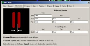
I can see how it would be OK for photo etching but for laser printer method its easier with bigger gaps.....still not massive, just a tad bigger helps. You can set that bit here:
Attachments
maxw said:I've found the default design rules for eagle not so suitable for DIY etching in some situations. I have changed the default distance between ground planes and traces but haven't worked out how to get the resister and small capacitor pads a bit bigger......if anyone know how then let me know
As far as I know the way to adjust the size of the pads and holes is to open the library file and edit the packages. This can be done while you have the board file loaded. Once you have modified the package save and close the package editor then go to Library, Update All. This sonds like a lot of work but it really only takes a few minutes as most designs don't use an exccessive number of different packages.
For laser etching I like to use a 0.01 drill size with 0.66 pads, especially on resistors. My problem is not with getting a dood toner transfer, it with undercutting during etching which leaves a very small trace, when you drill the fragile pad often lifts. Using a 0.01 hole still leaves a little pinpoint to help guide the dril bit, but you don't get the undercutting. Of course now that I have switched to HCl + Hydrogen Peroxide I get much less undercut and it is a very fast etch. 😱
Ohh...and by the way that does indeed look like a very nice amp, I will likely etch that design too and compare it to my own 😉
I have just started to make my own boards, and from the start I did drill the boards before etching. That would overcome the problem with pads lifting. Check out my first boards here, if you like🙂 http://www.diyaudio.com/forums/showthread.php?postid=655266#post655266when you drill the fragile pad often lifts.
George, otherwise I followed your procedure as written earlier in this thread😉 Thanks again.
Steen😎
I think absolutely you have to edit all the components in Eagle library whatever you do, they all are way to small.
I even think mine are small now, and now most pads are 76mil "round" original they where perhaps 40mil "octagonal".
I even think mine are small now, and now most pads are 76mil "round" original they where perhaps 40mil "octagonal".
Gcollier said:
For laser etching I like to use a 0.01 drill size with 0.66 pads, especially on resistors.
Dood, you mean 660mil? 🙂 or was it 0.066 🙂
tobias_svensk said:
Dood, you mean 660mil? 🙂 or was it 0.066 🙂
Uhhh... 66mil...obviously

I also tried the drill before etch (in my express PCB days). But again I had issues with undercutting...it did make alignment very easy though! One note to all toner transfer etchers out there, the brand of toner makes a huge difference, I have tried using the same paper on several printers and found that all transfered differently. I have heard that there are even different formulations within a single brand....No I don't have a favourite.
G.
What paper do you use when laser etching? is normal paper good or something else? I have seen som paper that looks like THIN white plastic, very smooth.
tobias_svensk said:What paper do you use when laser etching? is normal paper good or something else? I have seen som paper that looks like THIN white plastic, very smooth.
I use semi-gloss photo paper, its perfect. I dont suggest using normal paper. There are plenty of guides on the internet too.
tobias_svensk said:What paper do you use when laser etching? is normal paper good or something else? I have seen som paper that looks like THIN white plastic, very smooth.
maxw said:
I use semi-gloss photo paper, its perfect. I dont suggest using normal paper. There are plenty of guides on the internet too.
Ink jet "photo" paper works fine. The "Plastic" paper you describe might work as well. I have even used photocopier transparencies with no trouble, but they are not as good as photo paper with the exception that linup for 2 sided boards if really easy!
Gcollier said:As far as I know the way to adjust the size of the pads and holes is to open the library file and edit the packages. This can be done while you have the board file loaded. Once you have modified the package save and close the package editor then go to Library, Update All. This sonds like a lot of work but it really only takes a few minutes as most designs don't use an exccessive number of different packages.
Care to elaborate?? I can ge to the edit package part of a library but it says I can change it while its in use......tried unchecking "use" and no schematics/boards are open.

Let's say you are working on a design and having both schematic and board "windows" open... when they are open you also have a third "window" open the "control panel". Go there and choose open library, choose the right .lib file to open (like RCL if it is standard caps/resistors) after that you push the button that looks lika a chip (package) and choose right package (if you don't know wich go back to schematic window and use INFO button on the device you wich to know the package of.
Then, lets say your original footprint is a octagonal (and to small 🙂 ) push CHANGE -> shape -> round -> and push on the footprint -> now it's round, then CHANGE -> diameter -> whatever you like.
When your done push the save button and after that you don't have to close down the library window just change to board window and LIBRARY -> update all.
Was to tired to even know if you asked for an explanation, maybe someone else needed it 🙂
And english... readable? hope so... goodnight.
tobias_svensk said:Let's say you are working on a design and having both schematic and board "windows" open... when they are open you also have a third "window" open the "control panel". Go there and choose open library, choose the right .lib file to open (like RCL if it is standard caps/resistors) after that you push the button that looks lika a chip (package) and choose right package (if you don't know wich go back to schematic window and use INFO button on the device you wich to know the package of.
Then, lets say your original footprint is a octagonal (and to small 🙂 ) push CHANGE -> shape -> round -> and push on the footprint -> now it's round, then CHANGE -> diameter -> whatever you like.
When your done push the save button and after that you don't have to close down the library window just change to board window and LIBRARY -> update all.
Was to tired to even know if you asked for an explanation, maybe someone else needed it 🙂
And english... readable? hope so... goodnight.
That is fantastic! just what I wanted to know, thank you so much tobias 😉
maxw said:
Care to elaborate?? I can ge to the edit package part of a library but it says I can change it while its in use......tried unchecking "use" and no schematics/boards are open.
Hmm, not sure if you are experiencing some other issue, but it works fine for me.
1. Open the board file.
2. From Library on the main menu select OPEN, choose the library file
3. From Library in the editor window menu select Package
4. Select The package you need to modify.
5. Click the Display button (layers) and hide the tPlace layer
6. Select Change tool and Drill, click the elipsis and enter a size of 0.01
7. Click all the pads you need to change.
8. Click the change tool and select Diameter, choose your size then click all the pads to change.
9. Save the library file
10. Close the library editor
11. Click Library, Update all
That's it
maxw said:
Care to elaborate?? I can ge to the edit package part of a library but it says I can change it while its in use......tried unchecking "use" and no schematics/boards are open.
Hmm, not sure if you are experiencing some other issue, but it works fine for me.
1.
Member
Joined 2002
I still got those boards in the bag there George : O ) I'm thinking about putting them together soon i just need to order parts.. Any one got a volume motor pot deisgn to control the motor ?
jleaman said:I still got those boards in the bag there George : O ) I'm thinking about putting them together soon i just need to order parts.. Any one got a volume motor pot deisgn to control the motor ?
I posted a parts list for my boards earlier in this thread.
g.
Member
Joined 2002
It lives!!!
I have both channels singing, but it is not quite finished, as I am still waiting for my header connectors to be delivered. I had things working with alligator clips.
It sounds great!!! Easily as good as the virtually the same circuit I did on protoboard!
No oscillation, everything is stable. No hiss no humm. Good work! 😀
I will finish it up next week when my parts get here, until then you at least know it works. 🙂
Thanks Brian and N00ber and everyone else.
BTW I decided to use an unregulated +/-15V supply for now, later it will be a regulated +/-18V supply when that trafo gets here.
Thanks,
Russ
Member
Joined 2002
I'm looking at building a board for a 15/ - + psu a surface mountable psu tranformer..
ANy one help me locate this parts psu list. ?
ANy one help me locate this parts psu list. ?
- Status
- Not open for further replies.
- Home
- Amplifiers
- Chip Amps
- GC Preamp Suggestions