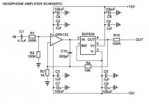
I have not seen many schematics being shown in this thread to go with the pcbs, so I just want to know if any of the board designs incorporate a cap in the same location as C10 in THIS schematic. I think I remember reading that it was a good idea, but correct me if I am wrong.
Attachments
We talked about that cap,incorporate a cap in the same location as C10 in THIS schematic. I think I remember reading that it was a good idea, but correct me if I am wrong.
go back to post #26 - #29 or thereabout🙂 I guess this thread is running a bit too long, to follow everything, said in here

CarlosFM recommended 200Pf, and PMA insisted that 18Pf was better. Alcaids curves shows that 200Pf is too much. I have used the 18Pf in that pos.
Steen🙂
BTW. Have you guys in mind to decide on a particular design for a groupbuy? I dont think the linestage can be much better, when looking at some of the designs here😎
Hi DC Dave,
go back one page: http://www.diyaudio.com/forums/attachment.php?s=&postid=637655&stamp=1115553605
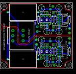
in that layout you find two small pads under the opamp, the left one is for R2, the right one for C10. You have to use smds at this position.
Better to use 4.7k for R4 and 470R for R3. For a headphone-amp you may (if you want) rise up gain to 21 (so done in the buf datasheet).
So you can see, the layout above can be used for 'your' headphone amp.
I'll still put all amp-modules (line loop, headphone and preamp) from carlos on a single euro pcb (100 x 160 mm) and post all data files in carlos' preamp thread.
Michael
go back one page: http://www.diyaudio.com/forums/attachment.php?s=&postid=637655&stamp=1115553605
in that layout you find two small pads under the opamp, the left one is for R2, the right one for C10. You have to use smds at this position.
Better to use 4.7k for R4 and 470R for R3. For a headphone-amp you may (if you want) rise up gain to 21 (so done in the buf datasheet).
So you can see, the layout above can be used for 'your' headphone amp.
I'll still put all amp-modules (line loop, headphone and preamp) from carlos on a single euro pcb (100 x 160 mm) and post all data files in carlos' preamp thread.
Michael
BTW: because of the higher gain you can use cheaper opamps (so you did in your schematic). You can also use a double opamp (OPA 2132), costs less then the single version and reduces layout dimensions (you need 2 capacitors and 2 elkos less than in single opamp version).
steenoe said:We talked about that cap,
go back to post #26 - #29 or thereabout🙂 I guess this thread is running a bit too long, to follow everything, said in here
CarlosFM recommended 200Pf, and PMA insisted that 18Pf was better. Alcaids curves shows that 200Pf is too much. I have used the 18Pf in that pos.
Steen🙂
BTW. Have you guys in mind to decide on a particular design for a groupbuy? I dont think the linestage can be much better, when looking at some of the designs here😎
The BUF634 app note talks about that cap and which combinations to use it with. In all honesty I tried the 18pf with my OPA627 version of this preamp and I think it was better without it. I am running with a gain of around 8 so stability is not a concern, I suspect if you were running at unity it might be more important.
G.
GeWa said:Hi guys
Just for the fun of it I made a small mod on the board.
I rotated all the caps 90° so they are all a bit closer to the op-amps.
A kind of a "carlosfm" touch
Cheers
Any chance you could post the Eagle file for this layout?
Sorry, but I don't have Eagle files of this PCB. I altered the image that was posted in post 381 with photoPaint.
Thanks for the clarification guys. I'm looking forward to seeing this project progress. I like the idea of such a compact versatile design.
DC Dave said:I have not seen many schematics being shown in this thread to go with the pcbs, so I just want to know if any of the board designs incorporate a cap in the same location as C10 in THIS schematic. I think I remember reading that it was a good idea, but correct me if I am wrong.
I started using the recommended 200pf cap.
Later I changed it for 47pf.
Smaller values are better.
Btw on your schematic the input coupling cap (C1), if you must use it, can be 470~680nf.
4.7uf with 100k to ground doesn't do much to remove DC-offset from the source.
carlosfm said:
I started using the recommended 200pf cap.
Later I changed it for 47pf.
Smaller values are better.
Btw on your schematic the input coupling cap (C1), if you must use it, can be 470~680nf.
4.7uf with 100k to ground doesn't do much to remove DC-offset from the source.
The only reason I chose the 4.7uf was b/c I have a bunch of BG caps in that value laying around. Is their a better value for the resistor in this case to remove DC offset? Or should I just ditch the BG in this application and go with the small cap?
DC Dave said:Is their a better value for the resistor in this case to remove DC offset?
The 100k resistor is fine for using with a 10k log pot, and as these op-amps are fet-input, the value is not critical at all.
DC Dave said:Or should I just ditch the BG in this application and go with the small cap?
Ditch it, and get a smaller one.
tobias_svensk said:
Thanks Tobais!

Hehe, have to correct you on my name a little bit.
The way you spell it it sounds like "To poop" in Swedish 🙂
Think of it as you have To Bias your OPA (or poopa? 😉 )
Yeye 😀
The way you spell it it sounds like "To poop" in Swedish 🙂
Think of it as you have To Bias your OPA (or poopa? 😉 )
Yeye 😀
tobias_svensk said:Hehe, have to correct you on my name a little bit.
The way you spell it it sounds like "To poop" in Swedish 🙂
Think of it as you have To Bias your OPA (or poopa? 😉 )
Yeye 😀
He He...I'll definately have to watch my spelling from now on...that is too funny! 😀

To Carlos:
in your poweramp improovement you put a 300nF Cap from + rail to - rail. Would you add this on the preamp too?
(just before i make the last changes in pcb-design... 😉 )
Michael
in your poweramp improovement you put a 300nF Cap from + rail to - rail. Would you add this on the preamp too?
(just before i make the last changes in pcb-design... 😉 )
Michael
slackman said:To Carlos:
in your poweramp improovement you put a 300nF Cap from + rail to - rail. Would you add this on the preamp too?
(just before i make the last changes in pcb-design... 😉 )
Michael
Yes, I use that cap with op-amps.
- Status
- Not open for further replies.
- Home
- Amplifiers
- Chip Amps
- GC Preamp Suggestions