In my PCB i skipped the rail-to-rail cap. because it would't fit 100% good on the PCB anyway i think. That cap. could be soldered directly to the socketpins from under (Wima MKS3, RM=7.5mm fits very good there) or perhaps a SMD cap. inside the socket in some way.
This is just really a bump to see, if we are all still alive.
May i suggest that a poll is conducted, to see IF the group buy does get under way, we have decided on a design that everyone is happy with. As i think the designs are all pretty much finished.
Other threads for the power supply, etc could be started and discussed there.
This may get the groupbuy idea rolling again.
EDIT, Wrote pole instead of poll, lol
May i suggest that a poll is conducted, to see IF the group buy does get under way, we have decided on a design that everyone is happy with. As i think the designs are all pretty much finished.
Good idea n00beR.
I myself am in favour of getting a board made.

Cheers
I am in for some boards, no matter what is chosen🙂 Most of the designs are really great.
Steen.
Steen.
re input pot
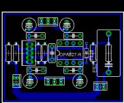
Question: With the diff pics of PCB
I may be wrong but:
I do not see a trace going to signal ground from the input to pot.
In other words there is not a voltage divider setup on the input
just a variable series resistance from In to to +input of Opamp.
It looks like only 2 connections to each pot.
Question: With the diff pics of PCB
I may be wrong but:
I do not see a trace going to signal ground from the input to pot.
In other words there is not a voltage divider setup on the input
just a variable series resistance from In to to +input of Opamp.
It looks like only 2 connections to each pot.
I do not see a trace going to signal ground from the input to pot.
It's connected to the groundplane.
Maybe an idea to split up the power- and signal groundplanes?
Cheers
GeWa said:
It's connected to the groundplane.
Maybe an idea to split up the power- and signal groundplanes?
Cheers
Thats what has been done on my board, however I lack the "onboard pot" that seems to be popular 😉
n00beR said:May i suggest that a poll is conducted, to see IF the group buy does get under way, we have decided on a design that everyone is happy with. As i think the designs are all pretty much finished.
I dont think there is any shortage of people interested and I think that once an actualy GB is posted there will be big interest......but there doesn't seem to be someone to do all the organising of the GB

Personally i'm going for a board without inputcaps and combined it with a motorized alps27 from dantimax the "Remote 1" i think
http://electronics.dantimax.dk/Kits/index.html
+
http://www.ettnet.se/~tobias/diy/opabuf/opabufwoic.jpg
http://electronics.dantimax.dk/Kits/index.html
+
http://www.ettnet.se/~tobias/diy/opabuf/opabufwoic.jpg
GeWa said:Hi n00beR
I believe this one is yours then.
Personally I don't mind whether there is a pot on the PCB or not.
Yup that ones all mine 😀😎
GeWa said:Still no volunteer?
My original intention when starting this thread was to have a group buy at the end. I haven't had any time latley to do anything as ambitios as a group by as I am crazy busy at work
 but if we can wait a few weeks I probably could be coerced into conducting one. We should definately conduct the poll to see what design we like...I still have a few changes of my own to offer....soon.
G.
signal ground
I am a real beginner so please excuse my simple question.
I notice on a couple of these cool PCB designs that the signal ground is seperate on the circuit from power ground.
My question is do the SG and PG currents ever come together at any point?
If they do come together is it off the PCB at some star ground say at the PS?
Thanks,
Russ
Gcollier said:
Input Buffer: BUF634
Gainstage: OPA637
I realize you corrected yourself on the order of the chips, I haven't read the whole thread, so forgive me if this has already been mentioned:
What about running say an AD8610 as an input unity gain amp, then the OPA637, followed by the BUF634?
In general the AD8610 wouldn't be useful, but if you were running off of a relatively low quality source, the low input bias current may be a good thing?
Just thinking out loud....
EDIT:...bad idea afterall. AD8610 has a higher input current, so it would actually be harder to drive than the 637....
Russ White said:no need for two opamps, just use either the 8610 or the 637. The 8610/20 are excellent.
Yea, it was a bad thought anyway wince the 637 has lower input bias current!

robselina said:
Yea, it was a bad thought anyway wince the 637 has lower input bias current!
I tested a range of pretty common opamps in a group listening session..we were all in agreement that the OPA627 sounded best in my design. The 637 had a level of crispness to it that almost sounded artificial. I didn't try the 8610/20. Also as I said earlier I removed the cap in the feedback loop of the opa627, it didn't seem to help any.
G.
- Status
- Not open for further replies.
- Home
- Amplifiers
- Chip Amps
- GC Preamp Suggestions