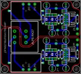
Ok, I felled the pressure 😉 to have the elcaps closer so i did another board. Now it also fits a 16x26mm inputcap like Mundorf M-Cap 2.2uF or simular.
I also skipped the terminals, because i'll just solder them directly anyways (from under).
Havn't decided yet if i'm going for a CRD/Resistor or cascade biasing.
with gp
without gp
3d
Thinking about using this PSU
psu schematic
top
3d
Cheers
I also skipped the terminals, because i'll just solder them directly anyways (from under).
Havn't decided yet if i'm going for a CRD/Resistor or cascade biasing.
with gp
without gp
3d
Thinking about using this PSU
psu schematic
top
3d
Cheers
tobias_svensk said:Ok, I felled the pressure 😉 to have the elcaps closer so i did another board.
That's a good pressure.
It's better.

tobias_svensk said:Now it also fits a 16x26mm inputcap like Mundorf M-Cap 2.2uF or simular.
Unnecessary.
I prefer to use that in the end: the power amp.
carlosfm said:Unnecessary.
I prefer to use that in the end: the power amp.
Yeah i now, but they fit there right now when the alps is there so hm.. well i don't know 😀
tobias_svensk said:Yeah i now, but they fit there right now when the alps is there so hm.. well i don't know 😀
Let it be, it's optional.
You can use a wire.
But in that case you should allow for different cap sizes, not only one.
tobias_svensk said:
In my opinion, you should put two caps before the regulator and 4 caps after the regulator. It's the inverse that you have there.
In my case, I add better results this way.
tobias_svensk said:Ok, I felled the pressure 😉 to have the elcaps closer so i did another board. Now it also fits a 16x26mm inputcap like Mundorf M-Cap 2.2uF or simular.
I also skipped the terminals, because i'll just solder them directly anyways (from under).
Havn't decided yet if i'm going for a CRD/Resistor or cascade biasing.
with gp
without gp
3d
Thinking about using this PSU
psu schematic
top
3d
Cheers
Tobais,
That is a fairly nice power supply design. It is actually very similar to what I am using right now on my OPA627/Buf634 pre that I posted here earlier, with the exception that I used larger filter caps up front. I can say that I am very happy with both the pre an the PSU, you likely should be too. 😀
I've been giving some thought lately about using precision voltage references as regulators something like ref102 and ref02 stacked as per the data sheet to give +15V out. Then using an opamp to invert the voltage to get the -15V. Followed by a pass transistor to boost the current handling. Am I crazy or what ???
 Do you think this type of design could povide the necessary current? Suggestions as always are encouraged!
Gcollier said:I've been giving some thought lately about using precision voltage references as regulators something like ref102 and ref02 stacked as per the data sheet to give +15V out. Then using an opamp to invert the voltage to get the -15V. Followed by a pass transistor to boost the current handling. Am I crazy or what ???
You stole my idea😡
I needed +/- 3v for digital pots, so I used a 3v reference, and ran it through a DRV134 to get both positive and negative 3v. I haven't built it yet due to the lack of time, but I'm guessing that it should work.
xplod1236 said:
You stole my idea😡
I needed +/- 3v for digital pots, so I used a 3v reference, and ran it through a DRV134 to get both positive and negative 3v. I haven't built it yet due to the lack of time, but I'm guessing that it should work.
tobias_svensk said:Hi Gcollier
Are you using yours to power both channels? I'm gonna have one for each channel
Tobias,
yes I am powering two channels off of the one supply. I just didn't have the caps for a second one. It still sounds very good. The way I look at it...one transformer, one supply. If I get a set of board mount toroidals I'll go seperate.
As for the vref idea...it should work very well, extremely low noise!
I just need to work on the design...unless somone has one 😉
Layout comments?
This post is becomming a bit dead again, and though I would give it a bit of a bump 😀
I see my layout has been down loaded 50+ times (ignoring the first "zip" post).
Has anyone built it yet, how does it sound?, or is it just rubbish 😉
Thx in advance
n00b
This post is becomming a bit dead again, and though I would give it a bit of a bump 😀
I see my layout has been down loaded 50+ times (ignoring the first "zip" post).
Has anyone built it yet, how does it sound?, or is it just rubbish 😉
Thx in advance
n00b
n00beR-
I sent you mail last week, I guess you didn't get it.
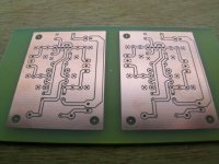
I etched a few of your boards, though I only have single-sided handy at the moment, to a added a groundplane to the trace side.
Send me mail with your address so I can mail you a pair.
I don't have the components to build them yet 🙁 but I shoudl be ordering this week (some double sided boards too).
I sent you mail last week, I guess you didn't get it.
I etched a few of your boards, though I only have single-sided handy at the moment, to a added a groundplane to the trace side.
Send me mail with your address so I can mail you a pair.
I don't have the components to build them yet 🙁 but I shoudl be ordering this week (some double sided boards too).
Attachments
WorkingAtHome said:n00beR-
I etched a few of your boards, though I only have single-sided handy at the moment, to a added a groundplane to the trace side.
Do you mean you have added a ground plane to the other sideof the board. (I.e. power ground on one side, signal ground on the other?)
No i never got your message i will go check it now and get back to you 🙂.
I have been too busy enjoying my new senn 600's this week

Thks again
n00b
GeWa said:Hi guys
Just for the fun of it I made a small mod on the board.
I rotated all the caps 90° so they are all a bit closer to the op-amps.
A kind of a "carlosfm" touch
Cheers
tobias_svensk said:GeWa, it was ment that Carlos should have comment that 🙂
I did it just for him 😀
Geez... that looks good.😎
GeWa, it was ment that Carlos should have comment that
Well, he already told us that about a million times so I wanted to make sure that he didn't had to do it once again and safe the poor man from cardiac arrest😉
Still no plans of manufacturing those boards.
Cheers
N00ber, I think it was the thread starter himself🙂 Read post #1, first line. I just stumbled over this comment, and rememberedI did search a little to find out who had made the multi channel comments

Steen🙂
Gcollier said:I am looking to build a multichannel preamp for a 5+ channel gainclone, this will be for home theater use.
Thanks
lol i knew some one had said it, didnt realise it was that far back hehe

Hehe GeWa 😉
Right now i have no plans for making any boards, as i'm poor
If someone wants to make some feel free to do so, please give me some more idees (like if someone really want that output resistor to ground etc)
One thing that can be done easy is to skip the input caps and rotate the ALPS 90 degrees (that way the motorized ALPS RK27 can be used)
Ch33rz
An externally hosted image should be here but it was not working when we last tested it.
PCB=2500x2500mil
ALPS RK27
El.Caps 6,3mm / RM=2,5mm (as big as possible)
100nF Caps = Wima MKS2 2,5x7,2mm RM=5mm
Resistors = RM 7,5mm
No input caps.
That's whats fits the board.
- Status
- Not open for further replies.
- Home
- Amplifiers
- Chip Amps
- GC Preamp Suggestions