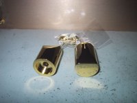
So do I. They look like being made the same place. Russel is offering a pretty good deal on those, no doubt. With that finish, it will be hard to find anything like it at that price. ( If at all possible!) Take a look at some tuning knops I ordered from THL. They are heavy. Weightwise😉 And nice if you ask me.In fact, I believe that is also being sourced from Taiwan.
Steen.
BTW the scratches on the end of the knop is my tablesurface that is mirrored🙂 🙂
Attachments
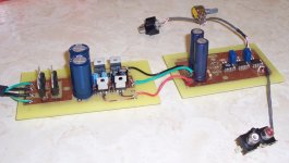
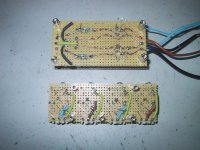
steenoe said:The Chip preamp is getting along. Have a look at the initial setup.
The boards are to the left 317/337 main psu witch feeds the LED regulator of Nuuk's next to the trafo. That will feed the linestage and the VSPS riaa. The main psu also feeds Alcaids CCS/Zener regulator that will feed the headphone amp in lower right corner.
.... Hope you can use some ideas Gcollier.
Steen.
Wow...go away from the computer for a day and look at what happens. Nice work Steeno 🙂 ....very inspiring, and yes LOTS of ideas!
I spent the dat yesterday working on a regulated power supply for my preamp. Right now it supplies +/-2.5V and +/-8V regulated and also +/-11.5V unregulated. The 2.5 V is for the DS1802 supply, the 8V supply is for the opamps, and the 11.5V unregulated is just there for the heck of it. Eventually I will increase the supply voltage to the opamps, but I need to get a different transformer...the one I'm using comes from an old UPS.
I also put together a small preamp board...not the one I posted earlier. This one has 2 AD843 for the left and right channel, an OPA134 on the ground channel. I'll post some photos on Monday when I get my digital camera back from the office.
My Weekend Project
Here are some pics of the project that I was working on this weekend. I got the headphone amplifier design from this thread over at headwize http://headwize.com/ubb/showpage.php?fnum=3&tid=5020&fpage=1
I belive that they call it the Morsel amp, there is a nice schematic from digi101. I modified the design a little so that it could accomodate either a virtual ground supplied by a buf634 (as opposed to TLE2426 in the original) if running of batteries. A standard ground from a split supply can also be used. You will see in the photo that the BUF634 is not soldered in, I don't need it since I am powering this from the regulated split supply in the photo (my other weekend project). For opamps I am using AD843 on the left and right channels, there is an OPA134 on the ground channel. I also added some 0.1uF decoupling caps whcih are soldered to the bottom of the board, near the supply pins...the boards are double sided. The gain is set to 10.
The sound is quite good, the wife commented that it was much more "clean" sounding than the previous OPA134 preamp I was using.
I'll likely be working on the OPA637-Buf634 design a bit more this week.
Attachments
That looks really good, Gcollier. Those regulators are quite compact. I see you have implemented reverse voltage diodes around the LM3##'s, Do you think they are necessary, or is it just for insurance? I didn't use them, but can quite easy adapt them at this time. The datasheet says that they are only really needed
if the rails are over 25 volts, if I didn't get it wrong
Steen.
if the rails are over 25 volts, if I didn't get it wrong
Steen.
steenoe said:That looks really good, Gcollier. Those regulators are quite compact. I see you have implemented reverse voltage diodes around the LM3##'s, Do you think they are necessary, or is it just for insurance? I didn't use them, but can quite easy adapt them at this time. The datasheet says that they are only really needed
if the rails are over 25 volts, if I didn't get it wrong
Steen.
Steen, as you said...the reverse voltage diodes are there for extra insurance. I wanted this to be a flexible design so I added them. For this particular supply I could just have easily left them out. I've been running the unit as is for now with no heatsinks, it barely gets warm...but then again i'm not droping the voltage much. I plan on cuting a couple of heatsinks from some aluminum then mount then to the LM3XX's, the supply diodes are unlikely to need any heatsinking....now if I could only find a good transformer for this project withthe right price...Free

These could work and the price is almost free. The seller says they are 12-0-12V. I've bought two but waiting for them to drop in my mail box.
edit:
link didn't work goto www.ebay.com and search for:
"Brand New Toroidal / Toroid Power Transformer 230v#
edit:
link didn't work goto www.ebay.com and search for:
"Brand New Toroidal / Toroid Power Transformer 230v#
Steen!
I know you have helped me more than i can posibly ask for, but...
that webshop has black gate caps.. 😱
I'v been dying to try a few of them for quite some time now..
so, you have my mail adresse 😀
-Marius
I know you have helped me more than i can posibly ask for, but...
that webshop has black gate caps.. 😱
I'v been dying to try a few of them for quite some time now..
so, you have my mail adresse 😀
-Marius
Alcaid said:These could work and the price is almost free. The seller says they are 12-0-12V. I've bought two but waiting for them to drop in my mail box.
edit:
link didn't work goto www.ebay.com and search for:
"Brand New Toroidal / Toroid Power Transformer 230v#
Alcaid, thanks for the suggestion, but that is barely more powerful than what I am using now....besides it is 230V input, and we are on 120V here in North America 😀 I do have a nice 750VA toroid sitting around...that should work fine for a preamp 😱 I may actually look into ordering a PCB mount toroid for this project, then design a regulated power supply around it, similar to what I have now.
Gcollier said:Alcaid, thanks for the suggestion, but that is barely more powerful than what I am using now....besides it is 230V input, and we are on 120V here in North America 😀 I do have a nice 750VA toroid sitting around...that should work fine for a preamp 😱 I may actually look into ordering a PCB mount toroid for this project, then design a regulated power supply around it, similar to what I have now.
750VA is nice, but WAAAAAYY overkill for this circuit 😉 I Use a 50VA 2x18V toroid Fforgot about canada using 120V, I just recommended something from your point of view regarding price: free.
Digital Pot For Preamp
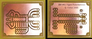
Ok so here is a shot of the board that I am using as the digital pot for my preamp project. The pot I'm going to use is a DS1802. I'll be feeding it +2.5 V and -2.5V to ground. I've added pads for Volume UP/Down, Balance L/R, and Mute, but will likely only be using the volume for now. I'll likely drill and populate this board tonight. I have a small spring loaded momentary switch that I am going to use to control the volume for now, but I plan on coming up with some kind of DIY volume knob, likely with a spring loaded return. 🙂
Ok so here is a shot of the board that I am using as the digital pot for my preamp project. The pot I'm going to use is a DS1802. I'll be feeding it +2.5 V and -2.5V to ground. I've added pads for Volume UP/Down, Balance L/R, and Mute, but will likely only be using the volume for now. I'll likely drill and populate this board tonight. I have a small spring loaded momentary switch that I am going to use to control the volume for now, but I plan on coming up with some kind of DIY volume knob, likely with a spring loaded return. 🙂
Attachments
Gcollier, looks good You are quite skilled at making those pcb's. Wish I could! Have to start on that too, sometime.
What method are you using? The tracks seems quite sharp edged. Good work.
Steen.
You are quite skilled at making those pcb's. Wish I could! Have to start on that too, sometime.What method are you using? The tracks seems quite sharp edged. Good work.
Steen.
steenoe said:Gcollier, looks good
What method are you using? The tracks seems quite sharp edged. Good work.
Steen.
Steeno, thanks for the compliments! I picked up 10 2 oz 18"x24" double sided boards on ebay for $35 CDN including shipping 😀 I
use one of two toner transfer methods to do the boards...sometimes a combination of the two. Basically I create my design in Eagle, print the top mirrored and the bottom normal onto HP or Epson glossy photo paper (currently using an old pack of glossy HP plotter paper). I scrub the boards with 0000 steel wool untile ther are nice and shiny. Then I take my printouts place them face to face (toner in obviously). I hold this up to the light and align everything carefully (really easy). You can tape the paper together so they don't move but I usually just hold it in place while I carefully insert the PCB between the layers. Next I take an iron set to the highest setting and iron the pattern onto one side, just until it sticks. Then I carefully fil over the whole works and do the same to the other side. Then iron...and iron some more...and iron some more on both sides...steam is optional 😉 With the HP and Epson paper I can tell when it's done because I start to see the pattern right through the paper. Next I soak it in a bowl of warm water for around 10 minutes until the paper softens and loosens...then peel it off. Typically there is residual paper stuck in the holes or between traces, just scrub this off with your finger...the resist layer is actually really tough and will take alot of scrubbing without peeling off if #1 your boards were very clean when you started, and #2 you ironed long and hard enough. You can touch up any ugly spots with a sharpie (I like the metalic silver ones for this) but typically with this method you won't have to. Then its into the etchant. I have tried both Ferric Chloride and Ammonium Persulfate and have no preference for either..with ammonium persulfate you can watch it etch, but for me FeCl is faster. For a small board I pour the etchant into a ziploc and put the board inside and squezze out as much air as possible. Then I put this in a second ziploc and stand it in hot water on a hot plate. Now watch the fun...if you want you can give the baggie a shake every now and then to help the etch. When the board is done I rinse it thouroughly with water then use acetone to remove the resist layer (you really have to scrub...as I said it's tough!). Finally I print my component layer mirrored onto a pice of laser transparency paper. Just line this up over your board and iron away...these things take an amazing amount of heat before they melt...I've used them to isolate chips from the heatsink before and neve had a problem. Anyway when you are done your ironing, cool the board under running water and slowly peel off the transparency. With 1/2 oz boards you will generally get a perfect transfer, with the 2oz boards I'm using it only sticks to the high spots as the traces are quite deep. Next thing to do is drill and solder and you are done! Byt the way you can also use the transparency method for your etch resist. I will do this sometimes if I have very thin traces that need to be perfectly aligned on top and bottom layers. If you have any sort of groundplane or wide copper traces the glossy paper is much better as it doesn't leave any pitting.
There was that long winded enough for you

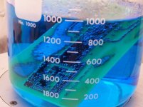
I attached a picture of a board being etched in ammonium persulfate, I made this one with the transparency method. You really should try etching your own boards it is much easier than you think, and I find is even easier for prototyping than breadboarding with all those damn jumpers and wires
Good Luck!
Attachments
Thanks a lot, for the "How to" description. I suppose you print on a laser printer? I will print your words and try this🙂 Long winding; yes but very interesting😉 Compared to P2P, etching your own pcb's probably isn't more timeconsuming? Take a look at this P2P.
Steen.
Steen.
Attachments
The nice thing about doing your own pcb's for prototypes is you can use surface mount parts. Better still, this eliminates the drilling step!
I guess you are right, but how on earth do you solder those small parts?The nice thing about doing your own pcb's for prototypes is you can use surface mount parts. Better still, this eliminates the drilling step!
Steen.
i like to glue them to their respectable positions using 10sec super glue, and then just solder. a nother idea would be to use a clamp on the desired part, if you have one small enough..
Actually its a lot easier than most people think. The easiest way ( for R's and C's) is to put a bit of solder on one pad, drop on a bit of flux then re-melt the solder and drop in the smd. Then solder the other pad. For chips simply tack down two diagonal pins, solder everything else, then touch up the pins. Solder paste makes it even easier, but most hobbyists don't have access to solder paste.
Tweezers, flux and solder wick are essential tools.
I have soldered TSSOP chips, and 0402 components by hand, quite successfully, with 3X magnifying loupes on my glasses.
Watch the vapour from that superglue! Its NASTY if it gets in your eyes.
Tweezers, flux and solder wick are essential tools.
I have soldered TSSOP chips, and 0402 components by hand, quite successfully, with 3X magnifying loupes on my glasses.
Watch the vapour from that superglue! Its NASTY if it gets in your eyes.
Watch the vapour from that superglue! Its NASTY if it gets in your eyes.
Yeah, but even nastier if you accidently inhale the stuff..
i swear i went blank for at least 15 secs, i woke up on the floor and got one hell of a headache not long after.

so i'v learnt to take my precautions..
oh well, back to PHP now..

TwoSpoons said:Actually its a lot easier than most people think. The easiest way ( for R's and C's) is to put a bit of solder on one pad, drop on a bit of flux then re-melt the solder and drop in the smd. Then solder the other pad. For chips simply tack down two diagonal pins, solder everything else, then touch up the pins. Solder paste makes it even easier, but most hobbyists don't have access to solder paste.
Tweezers, flux and solder wick are essential tools.
I have soldered TSSOP chips, and 0402 components by hand, quite successfully, with 3X magnifying loupes on my glasses.
Watch the vapour from that superglue! Its NASTY if it gets in your eyes.
I agree, soldering SMD is really not all that hard. I've seen various methods used, the easiest is to tack down the parts with superglue (as mentioned) then use broad soldering point and completly cover the pins with solder. Then just go over the works with a piece of desoldering braid. Check for any unwanted connections between the pads..if there are some cut them with a razor blade or X-acto knife. The other method is the toaster oven method. I tried this once with some junk parts I desoldered from a dead DVD player, it worked pretty well. I attached a link to the PDF file desctibing the process. You don't need the stencils and can apply the solderpaste with a syringe, or the point of a needle. http://www.pcbexpress.com/essentials/Stencil.pdf
- Status
- Not open for further replies.
- Home
- Amplifiers
- Chip Amps
- GC Preamp Suggestions