Gcollier
So the only thing that keeps the etchant from etching away the wanted (lines?) is the printers inc?
Shouldn't sodiumhydroxide, NaOH (Pipecleaner) work just as well?
And last, you are using boards without "photoresist" since you don't use a lamp, right?
So the only thing that keeps the etchant from etching away the wanted (lines?) is the printers inc?
Shouldn't sodiumhydroxide, NaOH (Pipecleaner) work just as well?
And last, you are using boards without "photoresist" since you don't use a lamp, right?
kmj:
Try the Biltema photo paper (23-771) if you have a Biltema near you. It's really good for the toner transfer method.
You have to use a laser printer to make pcbs.
Try the Biltema photo paper (23-771) if you have a Biltema near you. It's really good for the toner transfer method.
You have to use a laser printer to make pcbs.
Alcaid
Biltema, all guys toystore 😀
I do have one close so their paper is a given, thanks!
so if one uses this method it's non-photoresistic pcb's. And if one uses trasparent paper and a uv-light its photoresist?
Biltema, all guys toystore 😀
I do have one close so their paper is a given, thanks!
so if one uses this method it's non-photoresistic pcb's. And if one uses trasparent paper and a uv-light its photoresist?
kmj said:Alcaid
Biltema, all guys toystore 😀
I do have one close so their paper is a given, thanks!
so if one uses this method it's non-photoresistic pcb's. And if one uses trasparent paper and a uv-light its photoresist?
Correct!
Då Jävlar! (just have to swear a bit when it doesn't get censored)
Nice, then i'll just have to find a inc-printer, the optimal solution would be a used old black-only printer.... First of will be a preamp and a powersupply to a riaa, i think 🙂
Nice, then i'll just have to find a inc-printer, the optimal solution would be a used old black-only printer.... First of will be a preamp and a powersupply to a riaa, i think 🙂
kmj said:Då Jävlar! (just have to swear a bit when it doesn't get censored)
Nice, then i'll just have to find a inc-printer, the optimal solution would be a used old black-only printer.... First of will be a preamp and a powersupply to a riaa, i think 🙂
NO NO NO!
Don't use an inc printer. It will not work. You MUST use a laser printer. The tones will then melt and transfer to the copper.
Lazer? Even better, much easier to come by 🙂
edit, how the heck did i get the "Z" there?
Laser...
edit, how the heck did i get the "Z" there?
Laser...
Watch out, there are many scandinavians around here😀 BTW the toner for a laser printer is mostly a plastic compound with low melting point. That is propably why it is usefull for pcb making. Ask me about toner, I am a Reprotechnician😉 The toner as it is called, is actually a powder!Då Jävlar! (just have to swear a bit when it doesn't get censored)
If you want to know more specifically, the drums in a Copymachine, run about 115 dg. Celsius. The plastics are atttached to the paper by magnetizing of the paper by the Corona. Then fixed to the paper by the drums, being about the 115 degrees. With a little help of pressure, and the magnetics. The toner is ofcourse designed with this low melting point, so it is still possible to touch the copier. They do not run in Class A
🙂
New copiers work on other principles. Something like a toaster providing the heat here and now, as opposed to older models that were hot all day🙂 But I guess this is a bit off thread?
Steen.
If you want to know more specifically, the drums in a Copymachine, run about 115 dg. Celsius. The plastics are atttached to the paper by magnetizing of the paper by the Corona. Then fixed to the paper by the drums, being about the 115 degrees. With a little help of pressure, and the magnetics. The toner is ofcourse designed with this low melting point, so it is still possible to touch the copier. They do not run in Class A
Well, I do like to know HOW things work instead of only that it works, so i'm thankful for the OT . 😉
That would mean that what's protecting the coppertraces is a melted layer, now thats makes sence 😀
(I had a hard time grasping that inc worked as protection)
Yup you got it. I use uncoated boards, and the thin layer of toner (plastic) protects the board from the etchant. You can actually draw the traces with a sharpie (permanent) marker and it will etch fine too, but you need nice heavy coverage. Using "photopaper" also deposists a thin layer of claycoating that is on the paper embedded in the toner, thats why this works so well. Inkjet printers don't work because you cannot transfer the ink to your PCB. If you had an inkjet that used waterproof ink and could print directly to a PCB, you would be in business. There is actually a whole market for this opening up in commercial PCB fabrication, both for laying down resist layers and soldermasks etc....we can print to CDR's...why not a PCB. I suspect tht with the right ink formulation you could get one heck of a nice PCB from an inkjet, with as good or better traces than the photomethod allows! By the way I have used the photomethod, and it is very sensitive to the exposure time and the type and strength of developer you use...with the toner method there is less chance of a screw up...and uncoated boards are much cheaper.
And no...NaOH will not etch copper...you need to use an acid not a base. there is another way to etch with Hydrogen Peroxide and Hydrochloric acid...it is really fast, but I don't recomend doing it indoors.
Also you can silver plate your boards when you are done by cleaning them thoughourly then taking a cloth dipped in a mixture of dilute silver nitrate and KOH and wiping it across the surface of the board. I'ts a bit of a touchy process, but it does work 😉
Just bought a "kit". singlesided pcb, etchingpower, acrylic paint among other things. Probably more expencive that the parts by them selves but it works well to try on.
Damn, should have known that (chemist), just drew the fast conclusion that if it desolves aluminum then why not copper?
Anyway, here goes 🙂
And no...NaOH will not etch copper...you need to use an acid not a base. there is another way to etch with Hydrogen Peroxide and Hydrochloric acid...it is really fast, but I don't recomend doing it indoors
Damn, should have known that (chemist), just drew the fast conclusion that if it desolves aluminum then why not copper?
Anyway, here goes 🙂
New Layout Plans
Ok,
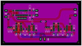
So I haven't got around to actually etching the board that I posted at the start of this thread...but I do have a revised layout for two channels, with an integrated DS1802 volume control. Please take a look and offer any suggestions for improvements. I may just abandon my initial Class A thought, I'm not sure it would really improve the design any. So what you see here is nothing more than 2 channels of the Pavel Macura design, with a DS1802. The input is at the left and output at the right of the board. Power connection for the DS1802 near the top (+/- 2.5 V) and the rest is at the bottom (+/-12V).
Ok,
So I haven't got around to actually etching the board that I posted at the start of this thread...but I do have a revised layout for two channels, with an integrated DS1802 volume control. Please take a look and offer any suggestions for improvements. I may just abandon my initial Class A thought, I'm not sure it would really improve the design any. So what you see here is nothing more than 2 channels of the Pavel Macura design, with a DS1802. The input is at the left and output at the right of the board. Power connection for the DS1802 near the top (+/- 2.5 V) and the rest is at the bottom (+/-12V).
Attachments
The Top
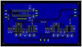
Here is the top
As you can see there is a groundplane on both sides, these are connected together with the vias near the decoupling caps. I had to do it this way since the ground on the bottom near these caps ended up being an "orphan".
Looking forward to any suggestions!
Here is the top
As you can see there is a groundplane on both sides, these are connected together with the vias near the decoupling caps. I had to do it this way since the ground on the bottom near these caps ended up being an "orphan".
Looking forward to any suggestions!
Attachments
When you guys talk about the OPA637, you are referring to the AP or BP version. I assume AP. I saw L on the board layout, but there is no L version, according to TI.
It means Left, none of the chips for the right section have lables
I.e.:
OPA637L = Left channel opamp
OPA637R = Right channel opamp
I.e.:
OPA637L = Left channel opamp
OPA637R = Right channel opamp
I dont know, you can't tell, but AFAIK the BP version has better input voltage offset and the specs of both of the chips are quite different,.
Check out the data sheet
You will also notice that the BP version is usually priced higher, due to the better spec.
But you wont be able to HEAR the difference.
Hope this helps
Craig
Check out the data sheet
You will also notice that the BP version is usually priced higher, due to the better spec.
But you wont be able to HEAR the difference.
Hope this helps
Craig
n00beR said:I dont know, you can't tell, but AFAIK the BP version has better input voltage offset and the specs of both of the chips are quite different,.
Check out the data sheet
You will also notice that the BP version is usually priced higher, due to the better spec.
But you wont be able to HEAR the difference.
Hope this helps
Craig
As far as the circut goes the choice of chip is insignificant, although I am using the BP version. And Yes L is for Left, I got lazy and haven't labeled all the components yet. I will also be trying this same circut with some AD843's which also have a nice "clean" sound IMO. The choice of input voltage is entirely up to you. I plan on etching this design very soon I will let you know how it turns out. 🙂
- Status
- Not open for further replies.
- Home
- Amplifiers
- Chip Amps
- GC Preamp Suggestions