All the series of 1N4XXX will be adequate.
Of course you can try with any 1A diode with Vf=1V or with two if the Vf is smaller.
Of course you can try with any 1A diode with Vf=1V or with two if the Vf is smaller.
Thanks ristar for your kind words.
Thanks Tibi for the quick support.
One diode 1Ν4007 is adequate to filter all glitches, although the dropping voltage wasn't bigger than 0.67-0.79V depending from attenuation point.
The current via the diode is very small at idle position (0,033mA-0,049mA) that increased via transition (max. 16+mA) but the total energy is very slow (max. 0,040mW).
Then, this solution will be reliable at all the time of R2R.
From my point of side, I would like to thank you the member Salas for his encourage to find a solution.
Thank you, lemon, for your time and investigation !
Regards,
Tibi
Hi Lemon, many thanks. I will follow your steps when receiving my board. Thank Tibi for quick response as well.
Hi Tibi,
Winstar WEH001602A is HD44780 compatible, which means I can buy it as replacement?
Just tested and is working without any firmware change, very, very well.
Thanks rogerchou !
OLED controller is fast enough to accept atmel quick commands. Therefore WEH001602A is a drop in replacement.
However, backlight menu option have no sense now, but this will be implemented in small firmware update.
Regards,
Tibi
Attachments
Last edited by a moderator:
From my point of side, I would like to thank you the member Salas for his encourage to find a solution.
Nothing much, you are welcome. Nice to know that my suggestion to you about lowering the relay coils feed VCC killed the glitches right away.
Just tested and is working without any firmware change, very, very well.
Thanks rogerchou !
OLED controller is fast enough to accept atmel quick commands. Therefore WEH001602A is a drop in replacement.
However, backlight menu option have no sense now, but this will be implemented in small firmware update.
Regards,
Tibi
Superb!!! It looks great.
Superb!!! It looks great.
Indeed, it looks far better than in picture.
Regards,
Tibi
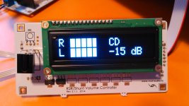
If it helps anyone, the Noritake CU16025 UW VFD Display does also work perfectly with Tibi's controller.
Edit: There's just a slight line below the volume blocks until the block is filled up.
Edit: There's just a slight line below the volume blocks until the block is filled up.
Just tested and is working without any firmware change, very, very well.
Thanks rogerchou !
OLED controller is fast enough to accept atmel quick commands. Therefore WEH001602A is a drop in replacement.
However, backlight menu option have no sense now, but this will be implemented in small firmware update.
Regards,
Tibi
Very nice!
Have in mind that the NHD-0216SZ-FSW-FBW from Newhaven Display works perfect with your controller.
The NHD-0216SZ-FSW-FBW is a large 99 mm x 24 mm viewing area display (Size: 122.0mm x 44.0mm).
More info at NHD-0216SZ-FSW-FBW NHD-0216SZ-FSW-FBW [122.0mm x 44.0mm] - $22.00 : Newhaven Display International, Inc., High Quality Standard and Custom OLEDs, LCDs and VFDs.
There is no compatible series 16 pin (it has 15,16,1...14 in series) but it is no problem, with the dupoint cables the problem has gone.

Tibi and dunzup.
Make us a present like different volume level setup per input for A/B test...and this Volume Controller will be the best!
Make us a present like different volume level setup per input for A/B test...and this Volume Controller will be the best!
great news, thanks for the troubleshooting Lemon, will try it asap
The different volume per input would be great indeed!
Its intended for hi-fi geeks after all, come on Tibi please the crowd 🙂
The different volume per input would be great indeed!
Its intended for hi-fi geeks after all, come on Tibi please the crowd 🙂
great news, thanks for the troubleshooting Lemon, will try it asap
The different volume per input would be great indeed!
Its intended for hi-fi geeks after all, come on Tibi please the crowd 🙂
We listen to the crowd and we'll do our best to implement.
You must know that we currently have almost reached atmel memory limit and processing power. This requirement is not something easy to implement and a large part of code must be rewritten. Be patient we are looking for a solution.
Regards,
Tibi
Same sentiment with regard to delivery for me😉
I just did the diode mod but no success for me... The pumpkin just takes time to warm up to reduce the offset. I guess it is something i have to live with. I may try to put another diode in series to see if it helps... But not holding my hopes up too much.
Some tips for others if it helps.... I found it really hard to pull the whole row of pins out to separate my balanced setup i was getting worried that my heatgun may damage the boards or relays... I ended up just removing the 6 pins on the opposite side and bending the row of pins just enough to gain access to the bottom.
I've not given up... Just reporting what i got that's all 😉
Ristar, it is pity that doesn't work for you. Of course you have cut the track, right?
Do you tried with multimeter the continuity of path? Perhaps, it has little of material and the continuity is still.
Do you tried with multimeter the continuity of path? Perhaps, it has little of material and the continuity is still.
Thanks for following up Lemon!
Yes I did verify the cut (it's a high quality board!) before soldering the diode. After the mod the resistance from cap to leg of both relays is above 14k also (was 0)
My preamp has a cap at output but the dc offset before cap at output is 1v before dropping to close to 0 as it warms up... I get about 80mV offset on the r2r attenuator output when everything is cold.
When this reduced the dc-offset, how is the behaviour of R2R? It pop-clicks or it is OK.
If it is OK, I think - but I am not very sure - that the R2R fw have the ability to 60" delay (as warm-up)...perhaps it helps!
If it is OK, I think - but I am not very sure - that the R2R fw have the ability to 60" delay (as warm-up)...perhaps it helps!
When this reduced the dc-offset, how is the behaviour of R2R? It pop-clicks or it is OK.
If it is OK, I think - but I am not very sure - that the R2R fw have the ability to 60" delay (as warm-up)...perhaps it helps!
The pop-click is not audible (most times) at the -16 to -15 transition. A soft pop/click is audible at the -32 to -31 transition. I actually tried to find the tube delay option - but couldn't find it in the current firmware. Is there something I have to enable for this to work?
Last edited:
I have in mind the following that I have bold & underline, at the 1st Tibi's message.
I will look to the documentation to see if there is any about it...
I will look to the documentation to see if there is any about it...
...
Specifications:
– low tolerance 0.1% R-2R network with melf resistors
– attenuation in 64 steps - each step 1dB
– Input resistance ranges from 20k to 1M for a Rload of 1M.
– Output resistance ranges from 9.75k to 10.5k.
– 4 selectable inputs with option to edit input name
– one direct input
– Infrared RC5 autolearning (can be used with any RC5 compatible universal remote)
– display back-light programmable On/Off - if Off timeout 10s
- large display characters for wide view
– tube menu for delaying plate voltage
– two open collector outputs for power On/Off and tube plate delay (see schematic J7 connector)
– AC power consumption, Max. 6W
...
Regards,
Tibi
- Status
- Not open for further replies.
- Home
- Group Buys
- GB for R-2R Volume Controller with 4 inputs