Yes, looks to be pin to pin compatible.
It may require a slight firmware change, but I need to buy one and test as well.
Regards,
Tibi
Good to hear that you are willing to modify new firmware for oled display since it is much better than lcd display in any aspect.
Good to hear that you are willing to modify new firmware for oled display since it is much better than lcd display in any aspect.
I also like OLED displays, but a LCD one will last considerably longer.
Regards,
Tibi
There is a very quick and dirty fix for this .Tibi, I like very much the R2R, but I must to find a solution to this issue because to my system isn't annoying only but I'm afraid for the tweeters.
I listen 3m far away and this glitch is audible, sometimes a lot.
.
But it have a downgrade : you will not hear signal when you adjust the volume ( and people need to hear when they adjust volume).
Do you want me to post this modifications despite that when press up and down volume you will not hear music ?
It involve one relay that strap output to ground whenever you adjust volume and release strap when you finished adjusting volume and one modified firmware.
Hi danzup and Tibi.
I don't think so, that I prefer no hear signal when I adjust the volume but it is an alternative method (except if this is correlated only for 32-31 and 16-15 attenuation).
Yesterday, I read the thread "Yet another Volume Controller...".
From what I saw, both of you had participated to this.
According to information that presented there, the issue summarized to:
1. Routing ground on PCB in a right way.
2. Recalc all Res values to make Rin and Rout lower down to 600 Ohm (for example)
3. Use RC circuit for each relay (for coil contacts)
4. Make a delay for relays switching
5. Avoid capacitive load
Please can you explain better what is meaning the (2) and if you could, can you increase the delay for relay switching only for 32-31 and 16-15 attenuation?
There is a very quick and dirty fix for this .
But it have a downgrade : you will not hear signal when you adjust the volume ( and people need to hear when they adjust volume).
Do you want me to post this modifications despite that when press up and down volume you will not hear music ?
It involve one relay that strap output to ground whenever you adjust volume and release strap when you finished adjusting volume and one modified firmware.
This will generate even huge plops. Instead to jump in small steps, with this solution you are generating a large step. At high volume may affect speakers are well.
Regards,
Tibi
Hi danzup and Tibi.
I don't think so, that I prefer no hear signal when I adjust the volume but it is an alternative method (except if this is correlated only for 32-31 and 16-15 attenuation).
Yesterday, I read the thread "Yet another Volume Controller...".
From what I saw, both of you had participated to this.
According to information that presented there, the issue summarized to:
1. Routing ground on PCB in a right way.
2. Recalc all Res values to make Rin and Rout lower down to 600 Ohm (for example)
3. Use RC circuit for each relay (for coil contacts)
4. Make a delay for relays switching
5. Avoid capacitive load
Please can you explain better what is meaning the (2) and if you could, can you increase the delay for relay switching only for 32-31 and 16-15 attenuation?
1. this to provide a solid ground and isolate r-2r network from external parasitic interferences
2. this will drop down IN and OUT impedance. It may be used in case where source have very low output impedance
3. decouple each relay in order to minimize any induction in relay switch
4. This is implemented in firmware. I prefer to keep this inhouse.
5. Any capacitive load add DC component.
Regards,
Tibi
Thanks Tibi.
No problems, understood about (4)...I don't ask to give us the code, either.
Please the (2) "this will drop down IN and OUT impedance. It may be used in case where source have very low output impedance" can you to expain me more?
In my case, my dac has 23 Ohm output and after this is yours R2R, after the R2R there is a DCB1 buffer and then Final Amp.
How is correlated this relation about In-Out? Is that meaning that must decrease the resistance input of buffer?
(sorry for my english...)
Last edited:
Thanks Tibi.
No problems, understood about (4)...I don't ask to give us the code, either.
Please the (2) "this will drop down IN and OUT impedance. It may be used in case where source have very low output impedance" can you to expain me more?
In my case, my dac has 23 Ohm output and after this is yours R2R, after the R2R there is a DCB1 buffer and then Final Amp.
How is correlated this relation about In-Out? Is that meaning that must decrease the resistance input of buffer?
(sorry for my english...)
It is about r-2r resistor network. You may change values to match a very low impedance. If network resistors are low, the associated plops are low even with a high parasitic DC current.
Now, if your preamp have 23 ohm output impedance he will behave differently with a load of 100ohm than 10K. You need to test before implement something like this.
Regards,
Tibi
Tibi,
What is the best solution about R42L & R43R, an 0R resistor, a simple jumper or a switch/channel?
Tibi,
What is the best solution about R42L & R43R, an 0R resistor, a simple jumper or a switch/channel?
R42L & R43R are 0ohm and are there to offer ground flexibility.
Normally L&R R-2R networks are completely isolated.
If you have a common ground, than you may need to connect all grounds all together and R42L & R43R may help you to do this.
Or maybe you want to go dual mono and R42L & R43R are not needed, or maybe you want ground L&R separately and, again, R42L & R43R are not needed, or maybe you want to ground L&R together but keep away from VC ground and so on.
Regards,
Tibi
Hi Lemon,
I'm following your updates with regard to your tweaks (especially because you have the equipment to really troubleshoot effectively!).
Tibi and Danzup, I have a low priority firmware bug to report. If you put the controller to standby after muting, on 'recovery' or powering on again, the "mute" text is flashing but music is playing (I discovered this by accident because I was having a conversation with someone and had to turn off the music and on resuming this occurred.)
Best,
I think that there is a alternative solution about clicking relay noise, without code changing.
I have tested this on oscilloscope with lower voltage at relay. I see that the glitches has gone completely when the voltage is below than 4.0V.
With acoustic test the glitch has hone from 4.2 and below completely.
Finally, the alternative solution could be different voltage for relays and 5V for the controller+display.
I am looking for what is the best, without a lot of modification on pcb.
Two 1N4001 diode in series will drop the voltage to ~3.8V. Put them only on +Vcc for relay section.
Regards,
Tibi
Regards,
Tibi
Last edited by a moderator:
Thanks tvicol for the info.
You meant to rise up the voltage output leg of L7805 and put in series two diodes to drop down the voltage? And for the controller+display power feed?
Maybe an external cable from voltage output leg of L7808 direct to Vcc ribbon cable of controller?
You meant to rise up the voltage output leg of L7805 and put in series two diodes to drop down the voltage? And for the controller+display power feed?
Maybe an external cable from voltage output leg of L7808 direct to Vcc ribbon cable of controller?
Thanks tvicol for the info.
You meant to rise up the voltage output leg of L7805 and put in series two diodes to drop down the voltage? And for the controller+display power feed?
Maybe an external cable from voltage output leg of L7808 direct to Vcc ribbon cable of controller?
No. I'll try to post some pictures later today.
Regards,
Tibi
Just want to acknowledge Tibi (really the Vicol Audio team) for responding so quickly to anything that crops up!
Looking forward to those pics (Lemon, thanks again!)
Looking forward to those pics (Lemon, thanks again!)
Thanks ristar !
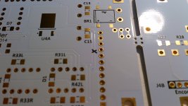
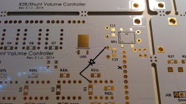
Here are promised pictures. Left picture indicate where you need to cut the track - see small black x, second indicate where to put 1N4001 diode. If one diode do not satisfy you, put second in series in same direction. Do not attempt to put the third diode as the voltage will drop under 3.7V and relays may barely work.
Regards,
Tibi
Attachments
Last edited by a moderator:
Thanks Tibi,
I'll try to take a closer look this weekend... hopefully there's enough space between the two boards to do this minor surgery (much more pain to unsolder that stretch of pins to separate the boards than this mod!)
Lemon, once again thanks for discovering this!
I'll try to take a closer look this weekend... hopefully there's enough space between the two boards to do this minor surgery (much more pain to unsolder that stretch of pins to separate the boards than this mod!)
Lemon, once again thanks for discovering this!
Thanks ristar for your kind words.
Thanks Tibi for the quick support.
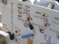
One diode 1Ν4007 is adequate to filter all glitches, although the dropping voltage wasn't bigger than 0.67-0.79V depending from attenuation point.
The current via the diode is very small at idle position (0,033mA-0,049mA) that increased via transition (max. 16+mA) but the total energy is very slow (max. 0,040mW).
Then, this solution will be reliable at all the time of R2R.
From my point of side, I would like to thank you the member Salas for his encourage to find a solution.
Thanks Tibi for the quick support.
One diode 1Ν4007 is adequate to filter all glitches, although the dropping voltage wasn't bigger than 0.67-0.79V depending from attenuation point.
The current via the diode is very small at idle position (0,033mA-0,049mA) that increased via transition (max. 16+mA) but the total energy is very slow (max. 0,040mW).
Then, this solution will be reliable at all the time of R2R.
From my point of side, I would like to thank you the member Salas for his encourage to find a solution.
Attachments
Thanks ristar for your kind words.
Thanks Tibi for the quick support.
One diode 1Ν4007 is adequate to filter all glitches, although the dropping voltage wasn't bigger than 0.67-0.79V depending from attenuation point.
The current via the diode is very small at idle position (0,033mA-0,049mA) that increased via transition (max. 16+mA) but the total energy is very slow (max. 0,040mW).
Then, this solution will be reliable at all the time of R2R.
From my point of side, I would like to thank you the member Salas for his encourage to find a solution.
No worries and thanks for the update. I guess this explains why the lower board doesn't glitch as loud (probably a small bit of voltage drop from the main board with the regulator to the "slave" board)
Will get round to doing this - need to pop by the local shop for the diodes.
- Status
- Not open for further replies.
- Home
- Group Buys
- GB for R-2R Volume Controller with 4 inputs