Hi Guys,
I have a quick question. I've been looking to source transformers in the US for the PSU but so far haven't been able to find any PCB mount trafo with the same pin outs, so my options seems to be to locate the trafo's off board. I'm thinking of using some small torroids that I have from Antek with dual secondarys for the 18v trafo and single secondaries for the 9v trafo. am I correct in assuming that I just attach the secondaries to the board at the PSB trafo secondaried as shown in the attached picture ?
Thanks,
PJN
Attachments
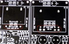
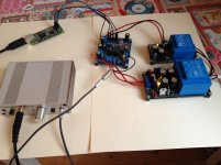
Yes, correct. Alternatively you can use screw type connectors (5mm lead spacing) on the boards to attach external transformer like in the picture below 😉
Attachments

Last edited:
Hi,
I just built the symmetrical power supply using the zeners and measured voltages without load: +14.01V and -15.35V.
Is this difference too much? What is the most likely cause? Try another 317/337 combination?
Thanks,
Michiel
I just built the symmetrical power supply using the zeners and measured voltages without load: +14.01V and -15.35V.
Is this difference too much? What is the most likely cause? Try another 317/337 combination?
Thanks,
Michiel
Never mind, spotted a bad solder and voltage is at +15.38V now.Hi,
I just built the symmetrical power supply using the zeners and measured voltages without load: +14.01V and -15.35V.
Is this difference too much? What is the most likely cause? Try another 317/337 combination?
Thanks,
Michiel
Received everything in good order! Thanks!
Just to be sure, D11 & D12 (zeners) go under the PCB directly on the trimpot pins, right ?
Just to be sure, D11 & D12 (zeners) go under the PCB directly on the trimpot pins, right ?
If you use the zeners for setting the voltage reference you must not use the trimpot and thus just put the zeners on top of the PCB.
@all:
I started making an assembly guide/instruction for the PSU but did not have enough time to complete it (remember this is my hobby). However since most have their boards now I thought it might be helpful to make the (unfinished) document available. Maybe some experienced builder want's to complete it 😉
curryman DAC PSU assembly guide v1.0.pdf
Also I would like to thank nautibuoy who made the very nice spreadsheet
kind regards, Daniel
Indeed Daniel. I need this assembly instruction badly because I am not so experienced. I hope with you that someone picks up your good work soon and completes the instruction. I am almost sure there are more inexperienced people like me.
Eric
Eric
Hi Ron and Daniel, I received my package today; nice job so a vote of thanks is in order I think.🙂
Now down to business. First project some of the PSU boards and DAC are destined for is a headphone amp. I'll be using three of the large PSU boards to power a hybrid headphone amp using an Erno Borbely circuit (2 * +/-15 for the power rails and +/-6.3V for the two valve (tube) heaters. I'll post pictures in due course.
Ray
Thanks for confirmation Ray. 🙂 . Glad that the patience paid out and you received the package finally.! ;-) . I had a little bit of a bad feeling about that you did't receive your order till yesterday.
And of cource we are curious about your project! 🙂 . Tomorrow my last exam and then I'll get to my projects.. Will also Post pictures in this thread!
Greetings Ron!
And of cource we are curious about your project! 🙂 . Tomorrow my last exam and then I'll get to my projects.. Will also Post pictures in this thread!
Greetings Ron!
Hi Ron and Daniel,
I have also received my package. Thank you for puting this together.
Too many projects, too little time.
Thanks,
Mogens
I have also received my package. Thank you for puting this together.
Too many projects, too little time.
Thanks,
Mogens
Well, it seems that my Reichelt packet might be waiting for me at home, at my neighbours or at the post office. I hope the GB half is also coming soon after delayed sending because of my vacation.
Guys, I need some help. I am in the process of putting together the PS boards and I am at a loss when it comes to:
The zener diodes -I understand they go into D11/12position of the larger board - but in which direction and does it matter which of the four holes I use?
The LEDs - which direction are they put in? The holes on the boards do look exactly the same to me, so where goes which leg - and is that the same with all (i.e. green and yellow) LEDs?
Your support will be appreciated - thx.
Did you realize the assembly guide in post #168? It includes some pictures that should make everything clear.
Sent from my GT-I8750 using Tapatalk
Sent from my GT-I8750 using Tapatalk
Yes, noticed the assembly guide, but in terms of LED orientation I wouldn't have minded more information and/or clearer pics - especially concerning the one next to R14.
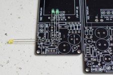
As per the schematic all LEDs are used in forward direction and cathode (short leg) goes to the more negative point (this is GND for the positive regulators and -15V for the negative regulator part). I see, some markings would have been better 
Hoping the attached picture helps.
Just to make sure: if you are unsure with the schematic (i.e. not that deep knowledge wrt electronics) you should ask an expert when it comes to attaching the board to mains voltage - can be dangerous 😱
Hoping the attached picture helps.
Just to make sure: if you are unsure with the schematic (i.e. not that deep knowledge wrt electronics) you should ask an expert when it comes to attaching the board to mains voltage - can be dangerous 😱
Attachments
- Status
- Not open for further replies.
- Home
- Group Buys
- GB for currymanDAC & PSU Boards