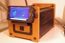
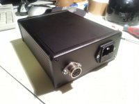
Nice job, Ray! What enclosure is that?
Thanks Max. I bought the chassis on ebay from the Chinese seller 'sep_store', search for 'BZ3207P'; the chassis was very good value (£42 including shipping as I recall) so I can forgive the few slightly rough edges.
Ray
Finally got a bit of time to put my dac and rpi in a box. How do you think, will be ok to put all together in a box with 2 tpa3116's in ptbl and switching
An externally hosted image should be here but it was not working when we last tested it.
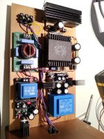
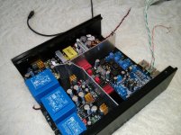
psu?Hi, I have made one of the boards with a 9VA transformer for Raspberry Pi with the standart bom, the board is the one on the right. But I think that psu doesn't provide enough current for rpi. The transformer is providing 500mA. Any help is appreciated. Thanks
An externally hosted image should be here but it was not working when we last tested it.
Hi, I have made one of the boards with a 9VA transformer for Raspberry Pi with the standart bom, the board is the one on the right. But I think that psu doesn't provide enough current for rpi. The transformer is providing 500mA. Any help is appreciated. Thanks
You need at least around 750mA to power a RPi from my recollection.
Remove the transformer from the board you've assembled and solder a terminal block in its place so you can connect a suitably specified off-board transformer. You will definitely need a substantial heatsink on the LM317 in this supply - I suggest you make use of the calculator spreadsheet that was posted a little while back to work out what is required. I think the rest of the components will be OK with that sort of load but don't take my word for it.
Another possibility I exploited when I needed 5V at higher current was to use one of the larger Curryman power supply PCBs but only populate the positive side of it and modify the underside of the board to parallel the secondary windings of the transformer. Not sure if this would be adequate for your purpose though as you can still only get a 10VA transformer on the board - don't forget to allow some headroom when specifying the transformer.
Ray
I'd second Ray recommendation. Use an external transformer, you'll need arround 750-800mA as a minimum. Transients may be even higher so dimension for 1A. The LM317 needs substantial headsinking, not sure if attaching to case side wall might be OK. Eventually you have to change
I'd recommend to place the offboard transformer in the upper left side of the enclosure to keep it away from the DAC. If you turn arround the 5V PSU you might be able to attach the Reg to the side wall.
What about the SMPS? Might get a bit overtight in this enclosure 😱
kind regards, Daniel
I'd recommend to place the offboard transformer in the upper left side of the enclosure to keep it away from the DAC. If you turn arround the 5V PSU you might be able to attach the Reg to the side wall.
What about the SMPS? Might get a bit overtight in this enclosure 😱
kind regards, Daniel
You need at least around 750mA to power a RPi from my recollection.
Remove the transformer from the board you've assembled and solder a terminal block in its place so you can connect a suitably specified off-board transformer. You will definitely need a substantial heatsink on the LM317 in this supply - I suggest you make use of the calculator spreadsheet that was posted a little while back to work out what is required. I think the rest of the components will be OK with that sort of load but don't take my word for it.
Another possibility I exploited when I needed 5V at higher current was to use one of the larger Curryman power supply PCBs but only populate the positive side of it and modify the underside of the board to parallel the secondary windings of the transformer. Not sure if this would be adequate for your purpose though as you can still only get a 10VA transformer on the board - don't forget to allow some headroom when specifying the transformer.
Ray
Found a quick solution. Thanks to everyone.
An externally hosted image should be here but it was not working when we last tested it.
Thank you all for your Pics of your builds! Kinda impressing!
That puts me into pressure finally completing my build and post here some pictures too! ^^
But flesh is lazy as hell! ^^
That puts me into pressure finally completing my build and post here some pictures too! ^^
But flesh is lazy as hell! ^^
Thank you all for your Pics of your builds! Kinda impressing!
That puts me into pressure finally completing my build and post here some pictures too! ^^
But flesh is lazy as hell! ^^
But haven't you been studying hard and sitting examinations so you've got a valid excuse!
How did that go by the way?
Ray
Hey Ray, thanks for asking.. Still studying and working and I have no or little time for hobbies.
The exams are done and I got very good grades. But medicine is time consuming like hell. But it makes fun to study this and it is really interesting!
Nevertheless I wish I had more time for hobbies like DIY Stuff (Audio/Robots/Linux etc..).
The PSU and CurrymanDAC with the AMANERO USB-to-I²S Board are still in the cardboard box! ^^
Around christmas I'll mabe have time to complete the majority of my diy projects.!
So thanks again for asking and thank you for your pictures. Really clean and nice build. And the case looks really nice. Looked for it on Ebay and aliexpress. Maybe I'll order such a case! I am a little bit jealous! 😉
So, greetings from germany...
Ron
Last edited:
Hey Ron, time to raise the pressure a bit more 😀
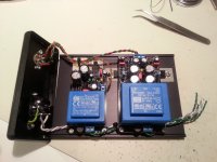
In the meantime I made a new small Powersupply for my USB-DAC (Amanero + Isolator + Curryman DAC) using the boards from the GB.
Furthermore I also changed the supplies of my RPi streaming client from a crappy SMPS to linear supplies.
So, my DAC and PSU projects are finished at the moment 😉
kind regards, Daniel
Attachments
rondadon, I did order one of those cases at ebay. It was delivered by DHL Express to my door. One hiccup though, I had to pay €23,11 for German customs and VAT to the courier. And as the DHL people do not carry change or card terminals with them, it had to be paid exact in cash.
rondadon, I did order one of those cases at ebay. It was delivered by DHL Express to my door. One hiccup though, I had to pay €23,11 for German customs and VAT to the courier. And as the DHL people do not carry change or card terminals with them, it had to be paid exact in cash.
I didn't pay any import duty on my one but it had a declared customs value of only $20.
Ray
Hi,
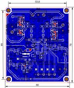
I’m trying to design a usb interface for the curryman dac with the same board dimensions so that it can be mounted above or beneath it. To connect the I2S signals I plan to place pins at exactly the same positions.
What are the precise mounting positions of the pin headers and the screw terminals? The only picture of the layout I found so far is the attached image.
Something else: Are the I2S inputs on the es9023 5V tolerant?
Attachments
USB interface
Hi,
that sounds like a really neat idea 😀
Maybe you can contact me via PN and I will be happy to help you with the necessary information.
I was also thinking about an input board with several inputs, e.g. SPDIF/AES/Toslink (WM8805) plus I2S for Amanero, however didn't have the time to develop such. Which USB to I2S converter IC are you planing to use?
Regarding the I2S inputs. I have a fairly old datasheet of the ES9023 which mentions a maximum input voltage of 5.5V for all 5V tolerant input pins but I couldn't find any information which pins are 5V tolerant 😱 I'll contact ISMOSYS regarding this info. Maybe someone else can help 😕
kind regards, Daniel
PM send regarding positioning.
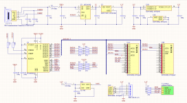
For the USB to I2S conversion I first tried to use STM32F4 MCU with my own custom firmware. It took me already 35 hours of work to get the USB audio connection working properly only to realise that I have no way to generate a precise bitclock for the I2S interface. That’s when I started looking for alternatives. I stumbled upon koon3876’s audio projects. His CPLD approach looked nice and because I wanted to teach myself HDL programming I decided go this route.
I attached the current (alpha) schematic for anybody who is interested. 🙂 Critique is always welcome.
Attachments
@nanonymous
The idea of a stackable USB interface for the Curryman DAC is really nice. Please keep us informed about your progress.
@daniel
Thanks raising the pressure. ;-) Just one month and I am done with this semester... Then I will have lot of time.
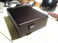
I am almost done with my Music player. Maybe I will try to put a Slot-In CD Drive into the case so I will be able to play CDs or dump them on the HDD.
Here two pictures. It's a miniITX Case. It will get small black spikes beneath.


My SymAsym also needs to be finished finally and also my SB 12 ACL Speaker need to be painted. So much to do! 🙂 .
The idea of a stackable USB interface for the Curryman DAC is really nice. Please keep us informed about your progress.
@daniel
Thanks raising the pressure. ;-) Just one month and I am done with this semester... Then I will have lot of time.
I am almost done with my Music player. Maybe I will try to put a Slot-In CD Drive into the case so I will be able to play CDs or dump them on the HDD.
Here two pictures. It's a miniITX Case. It will get small black spikes beneath.
My SymAsym also needs to be finished finally and also my SB 12 ACL Speaker need to be painted. So much to do! 🙂 .
- Status
- Not open for further replies.
- Home
- Group Buys
- GB for currymanDAC & PSU Boards