I have 6 CRCRC boards remaining, due to cancellation by member.
I will supply these 6 boards to following list.
List
maf_au 2 nos, pl share your details
windwardmt 2 nos., invoice sent
2 remain. grab'em.
I will supply these 6 boards to following list.
List
maf_au 2 nos, pl share your details
windwardmt 2 nos., invoice sent
2 remain. grab'em.
List
maf_au 2 nos, pl share your details
windwardmt 2 nos., invoice sent
taccodude 2 nos., pl share your details
maf_au 2 nos, pl share your details
windwardmt 2 nos., invoice sent
taccodude 2 nos., pl share your details
List
maf_au 2 nos, pl share your details
windwardmt 2 nos., to be shipped
taccodude 2 nos., to be shipped
maf_au 2 nos, pl share your details
windwardmt 2 nos., to be shipped
taccodude 2 nos., to be shipped
List
windwardmt 2 nos., shipped
taccodude 2 nos., shipped
please check your status and tracking number here below.
CRCRC GB LIST - Google Sheets
windwardmt 2 nos., shipped
taccodude 2 nos., shipped
please check your status and tracking number here below.
CRCRC GB LIST - Google Sheets
Last edited:
Thanks guys for the confirmation.
I have updated the sheet. Nearly 80% deliveries completed. Request others to confirm the receipt as and when delivered.
CRCRC GB LIST - Google Sheets
Regards
Prasi
I have updated the sheet. Nearly 80% deliveries completed. Request others to confirm the receipt as and when delivered.
CRCRC GB LIST - Google Sheets
Regards
Prasi
Prasi, I have a newb question about heatsinks for CRCRC board.
I saw (Use insulator below diode Heatsink) typed on the boards.
Is it so heatsink would be a bit lifted to not to heat the board?
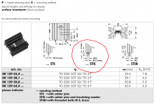
Should the type of heatsink like on this picture fit better?
I saw (Use insulator below diode Heatsink) typed on the boards.
Is it so heatsink would be a bit lifted to not to heat the board?
Should the type of heatsink like on this picture fit better?
Attachments
Prasi, I have a newb question about heatsinks for CRCRC board.
I saw (Use insulator below diode Heatsink) typed on the boards.
Is it so heatsink would be a bit lifted to not to heat the board?
Should the type of heatsink like on this picture fit better?
Hello Rainfallsky,
Yes, those are perfect.
The purpose is to insulate the bottom of heatsink rubbing away the solder mask in the long term and touch any vias.
One could also use following options
1. 1-2 layers of kapton tape
2. Plastic washers on the heatsiNk solder pins
Regards
Prasi
I just built the first of two boards that I plan to use in an Aleph J. I would like to offer some feedback on the CRCRC board.
The PCB was laid out without the use of thermal relief cutouts around the any of the component mounting holes. Many of the components were difficult to solder because the heavy copper areas dissipated the heat from the soldering iron too quickly. The big capacitors were the most difficult, and the 3W resistors were nearly as bad. I use a 75 Watt soldering station with electronic temperature control, and had it set for 435 degrees C. Getting a complete melt on the ground plane vias required a full minute or more.
If there is another build of the CRCRC board, I would like to recommend that thermal reliefs be used for mounting holes in the large copper areas.
Thanks for the feedback.
All the boards manufactured till date didn't have thermal relief including the 600 odd boards of CRC by member Project 16.
The technique that I use to solder boards with large ground planes is as below.
I use 2nos. 30 W irons and heat up the pad with a bit of solder for about 5-8 sec. And then touch the pad for 3 sec with solder wire melting.
This gives me good solder connection.
I also ensure that there is no air draft around like fans, etc to carry the heat.
Hope this helps.
Regards
Prasi
I feel that the thermal relief may increase impedance espcially for high current psu.
Another important thing I missed out above. The PSU is a source of very high heat (diodes, bulk caps and power resistors, etc). So copper planes on top and bottom would help in dissipating some of it, ensuring longevity. thermal reliefs would prevent such dissipation.
P.S. My logic may be flawed, so I invite comments from experts also, if any.
P.S. My logic may be flawed, so I invite comments from experts also, if any.
Prasi's advice is good, and similar to what I've seen AndrewT suggest previously (i think in a discussion about the dyiaudiostore universal PSU PCB). That board also features large pads and ground planes that help dissipate some of the heat, but require extra care in soldering.
- Home
- Group Buys
- GB: CRCRC PSU