Hi GnuB.
I have ordered some more pcbs of tht lt4320.
You could wait for few days.
Once they are available, I will contact you.
regards
prasi
I have ordered some more pcbs of tht lt4320.
You could wait for few days.
Once they are available, I will contact you.
regards
prasi
prasi, I'm still waiting for 2 picoDumbs to release his 4U 500mm chassis, so I'm not in a hurry.
REGULAR CRCRC PSU with smd LT4320 add-on option* X 2
SMD LT4320- pairs X 2
THT LT4320- pairs X 2
Thanks
REGULAR CRCRC PSU with smd LT4320 add-on option* X 2
SMD LT4320- pairs X 2
THT LT4320- pairs X 2
Thanks
prasi, I'm planning for a dual mono PS, so please add one of your cap multiplier boards (or 2 if necessary).
Thanks
Thanks
ok, i will check if i have the mark johnson-gtose cap mx pcbs.
else i will share the order link for it for pcbway boardhouse.
else i will share the order link for it for pcbway boardhouse.
Hello all,
I have 15 nos. of CRCRC PSU PCBs left in my stock. I want to get rid of the stock and hence selling at discounted prices. original price was usd 9 a piece.
I am offering it at usd 6 a piece.
if anyone wants a few, please share your paypal email, postal address with me via PM.
regards
prasi
I need to make provision for buying v-fet lottery amp kit 😉
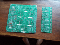
Boards received today.
As at least one other buyer has remarked, these are seriously heavyweight boards. And the multiple options provided for will allow me to use parts I already have.
Many thanks.
David
As at least one other buyer has remarked, these are seriously heavyweight boards. And the multiple options provided for will allow me to use parts I already have.
Many thanks.
David
Thanks David
All the best for your build.
Those were the last ones remaining and may never be manufactured in 2.4 mm thickness again as there is no material at my manufacturer.
All the best for your build.
Those were the last ones remaining and may never be manufactured in 2.4 mm thickness again as there is no material at my manufacturer.
Could you share Eagle Cad files or gerber ?Hello X , thanks.
Here are the schema and BoM for both versions of the ideal bridge rectifiers.
ver1. without AC snubbers (smaller PCB- 21.5mmx30mm)
ver2. with AC snubbers (bigger PCB- 25mm X 30mm)
I was unable to include these in all the packages as I ran out of rectifier PCBs.
The BoM attached is for the rectifier with snubber components.
I had in mind , the SQJB00EP mosfet , which is will generate about 10mW/ amp more than the mosfet you suggested above. Still should work well in the design.
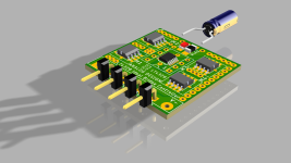
Regarding the LT4320 package, I have incorporated options for both DFN as well as DIP08 package. Only those who are good with smd soldering may attempt soldering DFN package.
here is an example by EEVblog guy
YouTube
regards
Prasi

Hi Prasi,
Can these rather large LT4320 Active BC's (50mm x 34mm) be fit to the CRCRC boards. If this can be accomplished, could you explain a bit how I would attach them together. Thanks for the help.

Can these rather large LT4320 Active BC's (50mm x 34mm) be fit to the CRCRC boards. If this can be accomplished, could you explain a bit how I would attach them together. Thanks for the help.
hi kokanee,
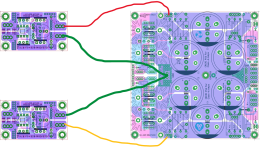
unfortunately, those are THT rectifier pcbs and those wont fit directly on the CRCRC PSU PCB, although one can run wires from THT rectifier output to the CRCRC DC+ GND and DC- pads marked on the pcb.
If you also have the SMD LT4320 rectifer PCBs, then assembled pcb can be mounted directly in 4 holes marked in below pic. Also attached is the 3d model of the assembled smd lt4320 rectifier.
hope, that makes it clear
Attachments
Thanks for the reply. Is the THT rectifier pcb output V+ and V-. ? If so, would one run 3 wires from V+ and V- to the DC+ and DC- on the CRCRC. Maybe you can mark up the pics to illustrate. Thanks.
V- of the positive rectifier and V+ of the negative voltage rectifier are connected together to form the ground and connected to GND TAB of CRCRC.

Thanks Prasi,
I thought those bridge controller pcb's were going to be useless, But maybe I can use them w/CRCRC pcb for some other Class A or Class A/B projects. Would be nice to not have all the HS/diodes to contend with.
I also have the 4320/CRC pcbs that I need a home for.
I thought those bridge controller pcb's were going to be useless, But maybe I can use them w/CRCRC pcb for some other Class A or Class A/B projects. Would be nice to not have all the HS/diodes to contend with.
I also have the 4320/CRC pcbs that I need a home for.
Kokanee, here's what I did to mount the boards, it may be of some help to you. Utilising enameled copper wire, of course.

Last edited:
- Home
- Group Buys
- GB: CRCRC PSU