Thanks for the answers, Algar!!
If it helps anybody, here is my project BOM.
It's missing the RCA connectors because they're too much money at Mouser and the IEC connector is missing as well because I decided going with a chassis mounted switched one.... Still investigating if it will fit...
Here are the instructions to access the BOM:
When you are ready to access your project again you can do so by using either of the following 2 methods:
1. Save the link listed below and enter that link into your web browser at anytime.
Mouser Electronics
2. Go to our Project and Cart Sharing page and enter the Access ID number below.
Enter Access ID: 0455536e79
R105 in schematic calls for 392K, but the pcb printed 332K.
May i know which is the correct value ?
May i know which is the correct value ?
R105 has two different values depending on what NP schematics you looking at: 332K from the original Firstwatt article, 392K from the Christmas Gift pcb (also from the pcb that was offered from the diyaudio store). I used the value marked on the PCB. The Nutube plate impedance is so high that I don't expect that much difference in the circuit with either value, but I never tried the 392K so I can't comment on the circuit difference, if that is any. Thanks for pointing that out.
SB
SB
As I said earlier, I placed a small order of other pcb, and ordered 5 extra B1 Nutube pcb, just in case some pcb get lost. It also mean that I still have a few if someone is still interested, until they last. Let me know.
Thanks
SB
Thanks
SB
Hi SB my board has not yet been delivered to me in the UK. How much longer should I give it before getting worried?
R105 has two different values depending on what NP schematics you looking at: 332K from the original Firstwatt article, 392K from the Christmas Gift pcb (also from the pcb that was offered from the diyaudio store). I used the value marked on the PCB. The Nutube plate impedance is so high that I don't expect that much difference in the circuit with either value, but I never tried the 392K so I can't comment on the circuit difference, if that is any. Thanks for pointing that out.
SB
I think Pass himself said anything 290-392k works just fine.
Hello all. I'm going to use a remotely mounted IEC power input connector (likely this part number 693-6100.3300) so I can wire in a double pole switch for the AC supply. Should I try to keep this power switch addition at the back panel end to keep the AC noise away from the B1 amp stuff? Or can I run twisted wiring up to a front panel mounted power switch? Thanks.
AC is always best kept well away from the signal so I would personally keep the mains at the rear, but that's not very convenient.
Will you be using the Hammond chassis specified in the BOM? There isn't a great amount of room to allow for separation between the wires and the board.
It may be ok so perhaps lay it out without the front and back panels and see how it sounds. It won't be a great hardship to switch to rear mounted then if it is too noisy.
Thanks avtech23. I probably wont be using the Hammond case. I've recently acquired easy access to a laser cutter and plan to make a plywood box for it so no dimensional constraint.
In that case, you should be ok to run a switch to the front.
Take mains along one side of the chassis and any inputs on the opposite side and leave a decent space between the wiring and the PCB and it will probably be ok.
When using a wooden chassis with a mains carrying switch, I normally connect the switch body with an earthing cable to IEC GND. I just don't trust mains switches enough to not end up live at some point due to an internal fault..
*Edit* I also fuse at the inlet to the chassis, before the switch.
Please share some photos of your build, laser cut ply sounds interesting!
Last edited:
Thanks so much for the advice avtech23. Especially the safety tip about putting the fuse before the switch. I’ll look into getting an IEC inlet with integral fuse holder. Yes, photos will be shared for sure.
C13 is missing from the 28 Feb BOM by the way. Make sure you order an extra cap same as C10, C11, C12: 1000uF, 16V, Panasonic FC Series EEU-FC1C102S (or whatever series you chose)
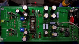
I'm gonna bask in the heat of those glowing green eyes, while I wait for more supplies!
I'm gonna bask in the heat of those glowing green eyes, while I wait for more supplies!
Attachments
- Home
- Group Buys
- GB B1 Nutube PCB with integrated PS