analog_sa said:
No obvious advantages but a real risk to disbalance the chips. Why use 0.1% resistors if there will be a mismatched pot?
The won't be any mismatching in a pot, if you use one of those http://www.diyaudio.com/forums/showthread.php?s=&threadid=3279&highlight=sonic+frontiers
😉
I don't get it!
While I'm completely in sync with KYW's reasoning here; http://www.diyaudio.com/forums/showthread.php?postid=115353#post115353
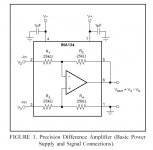
When I also look at how for example the ina134 is internally configured for maximum CMRR, I get a little confused
Anyone knows/care to explain this? (Balancing the impedances)
While I'm completely in sync with KYW's reasoning here; http://www.diyaudio.com/forums/showthread.php?postid=115353#post115353
When I also look at how for example the ina134 is internally configured for maximum CMRR, I get a little confused
Anyone knows/care to explain this? (Balancing the impedances)
Attachments
Opa541ap
Well, I got a little tweaky tonight also, so I wired up a circuit derivation with the opa541. I am using the industry standard differential input circuit. I figured as I was in the process of tossing out components I also dropped the coupling cap between V+/V- and the output R (I guess my opa541's aren't current limited then😉 ).
And I can tell you; it sounds really good! Since I can't measure the CMRR, I use the input from my PC which is 15m of unshielded cable. This in converted to a balanced signal in my BZLS, and carries a noise component on both phases. I couldn't detect any difference in the noise amplitudes between the circuits.
To my big surprise, I now like the opa541 the best of all the chips I have tried so far. I have also learned a few other things; there is no way one can compare the different power-op's except to swap them in and out of the same circuit/amplifier. They sound so different depending on component choice, psu, enclosure, wires, schematic etc etc. I have also learned that I much prefer gainclones driven by my BZLS to the passive standard one. And I use the Zapfilter from LC in my CDP, so it's not a drive-limited thing.
Next weekend I'll probably try the much hyped LM3875 that Tor M is sending me (-BIG thank you Tor!) with the same circuit and report back.
Oh, and btw -DC-offset also went further down 1/10mV
Happy tweaking!
As to the question in post#83, I guess I can explain it myself; The loss of CMRR from doing it this way isn't such a big deal in audio circuits😉
Matttcattt said:would 1.5uf across the power lines be ok? i cant get 1uf.
yes thats fine😉
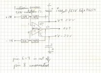
Mad_K said:I forgot; the new schematic:
I guess pin 8 should be connected to Vout. According to http://www-s.ti.com/sc/psheets/sboa057/sboa057.pdf (Table 1.)
This shoud give a 10A peak CL.
Mad_K said:As to the question in post#83, I guess I can explain it myself; The loss of CMRR from doing it this way isn't such a big deal in audio circuits😉
I'm not so shure there is a loss in CMRR.... the ina134 has 90dB (with laser-trimmed resistors
)Mad_K said:
I'm not so shure there is a loss in CMRR.... the ina134 has 90dB (with laser-trimmed resistors
That's actually correct. This way (ref. last schematic) we get the highest CMRR, but the impedances don't match. This leads to an imbalance in the balanced signal when the source has more than 0 ohm output impedance (as with the BZLS, especially with 10K out-pot). As long as you are using it as a balanced converter, this performance is poor anyhow, so I guess it doesn't matter. But if you have a nice balanced signal (as you would if the BZLS is driven by a balanced source), and wanted to balance the impedances, I guess we need to add a buffer.
Ref http://www-s.ti.com/sc/psheets/slod006b/slod006b.pdf
->chapter 3.5
This is a nice piece of read, and should be mandatory for all gaincloners! (including me😉)
Lm3875
Yepp, I've put in the LM3875 in my amp...
Well, what can I say?
-I still prefer the OPA541🙂
Somehow I was kind of expecting the LM chip to be better.
It is also more prone to oscillations -my right channel was oscillating like crazy with no input connected.. To my big surprise I got the best results by using the minimized circuit (10K+100K, +in to gnd), driven by -OUT of my BZLS. With this setup I had 2mV DC-offset in both channels😉.
What I have learned during the past six months of gaincloning is that it does not matter that much wich chip you use, but rather HOW you use it. I'm thinking about everything else but the actual chip; circuit, components, case etc.. I guess everyone will have their favourite chip given all the factors that go into making this kind of amp.
The great thing about all this is that it is much easier (or was it difficult) to make the amp sound excactly the way you want it🙂
My Gainclone is getting HOT!
I cannot believe how good it sounds!
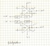
Today I tossed in a couple of OPA549's in a bridge-arrangement, to satisfy my curiosity. And, WOOOOOOOWWW, it sounds incedible
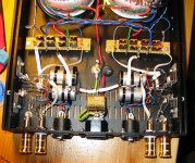
I know this is not an ideal setup for a bridgeclone, but I just wanted to check it out. The psu is too small.. But it does have a lot more dynamic range now. It throws out bass lines like a big p-p class A amp. Also I noticed alot more ambient cues, and 3D-effects (like q-sound) are insane. Distortion must be lowered. DC offset is 1-10mV.
Now it is time to do this proberly. I think I'll buy some bigger (and even better) caps to take some of the load of my poor little toroids.
Now I have really been bitten by the GC bug for shure; I'm going through my records like a madman
For those who dare to look at my dangerously p2p air non-insulated connections, I am enclosing a picture of the current state of the amp...
I cannot believe how good it sounds!
Today I tossed in a couple of OPA549's in a bridge-arrangement, to satisfy my curiosity. And, WOOOOOOOWWW, it sounds incedible
I know this is not an ideal setup for a bridgeclone, but I just wanted to check it out. The psu is too small.. But it does have a lot more dynamic range now. It throws out bass lines like a big p-p class A amp. Also I noticed alot more ambient cues, and 3D-effects (like q-sound) are insane. Distortion must be lowered. DC offset is 1-10mV.
Now it is time to do this proberly. I think I'll buy some bigger (and even better) caps to take some of the load of my poor little toroids.
Now I have really been bitten by the GC bug for shure; I'm going through my records like a madman
For those who dare to look at my dangerously p2p air non-insulated connections, I am enclosing a picture of the current state of the amp...
Attachments
Thanks😉
Mad_K = Mad Kontrol* / Mads Kristian
(Control in Norwegian= "Kontroll")
LMAO=?

And btw; the HS are now getting hot at party levels😉 I guess my speakers like some voltage..
Mad_K = Mad Kontrol* / Mads Kristian
(Control in Norwegian= "Kontroll")
LMAO=?
And btw; the HS are now getting hot at party levels😉 I guess my speakers like some voltage..
Mad I was laughing because of your all out effort on building the amp and it reminded me of tool time Tim (a tv show here) it was a compliment😉
Cheers!!The DIRT®
Cheers!!The DIRT®
I see😉 Thanks Dirt!
I know I become a bit obsessed when I'm in the middle of a project,
but I thought that I'd share my experiences with you guys. I see that there are noumerous questions in other threads regarding many of the issues I'm covering here so I recon you appreciate the info. If I'm brief or short it's either that I am short of time, or not to confuse anyone (or myself). There has been little response, so either people are getting it all, or it is not interesting.
I recon the building of the amp to be complete, now I'm just tweaking, exploring and learning a whole bunch of stuff. Very interesting. KYW recomends to put a 100K to ground before the 10K when used as a poweramp, so I think I'll put in one tomorrow.
Happy tweaking and (hopefully) listening everybody
- Status
- Not open for further replies.
- Home
- Amplifiers
- Chip Amps
- Gainclone with pseudo-balanced input?