More credibility
Peter, if you can see little bit of my work, look at www. GMX.cz. On maim page click at "....High End 2003 " and there look at TCC 301 ( power conditioner with insulating transformer ) and TCC 201 ( power amp + modules ). Text is in czech language, but photos not 😎 . Maybe after that my " credit " will be bigger for you.
Peter, if you can see little bit of my work, look at www. GMX.cz. On maim page click at "....High End 2003 " and there look at TCC 301 ( power conditioner with insulating transformer ) and TCC 201 ( power amp + modules ). Text is in czech language, but photos not 😎 . Maybe after that my " credit " will be bigger for you.
" talker or complainer "
Variac : no , I am not. Maybe twony five years I have my own constructions and similar things like on photo you can see by me only in case, when I try something and I mean, that DIY may be made the same like for example Madrigal or Classé products. " All that jazz " or " All that care ", is't true ?
Variac : no , I am not. Maybe twony five years I have my own constructions and similar things like on photo you can see by me only in case, when I try something and I mean, that DIY may be made the same like for example Madrigal or Classé products. " All that jazz " or " All that care ", is't true ?
Re: Mad K, where'd you get your amp cases?
they're from elfa.se/no and is called ds2480 (cheap -like $75)
darkmoebius said:I've been following this thread and have to say congratualtions and thanks for posting your adventures. I'm ordering parts this week to make a copy of Joe Rasmussen's(Sp?) Tube-buffered inverted GainClone (derived from more of Kui's work).
Anyway, I'm looking for a good chassis to house it all. And how much do they cost?
Thanks for all the work,
Darkmoebius
they're from elfa.se/no and is called ds2480 (cheap -like $75)
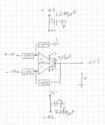
hmm, thats interesting, probably the least balenced circuit works the best? was there no point to a balenced circuit, or just not needed? looks like CMRR falls terribly fast on the lm3875s though. the opa541s seem to be better at that part. any RF supression used on the inputs of either?
With the 10 ohm (per phase) output Z from my XBZLS there will be a 0,00078dB signal imbalance on the two inputs....
I have no RF supression on the inputs.
😉
I have no RF supression on the inputs.
😉
no, i mean the input impedace of a diference amp is only conditionally equal, thus it is only conditionally balenced. for non-inverting input it is 110k in your case. for the inverting terminal however, it will be determined by the voltage at the non-inverting terminal, and will be 10k with 0v at the noninveritng input.
so at best noise rejection becomes a function of noise. this would be better for balenced lines in which there is no inverted line.
i'm assuming you have no noise issues and thus don't even need it to be balenced, as any attempt to decrease external noise will increase internal noise.
so at best noise rejection becomes a function of noise. this would be better for balenced lines in which there is no inverted line.
i'm assuming you have no noise issues and thus don't even need it to be balenced, as any attempt to decrease external noise will increase internal noise.
theChris said:no, i mean the input impedace of a diference amp is only conditionally equal, thus it is only conditionally balenced. for non-inverting input it is 110k in your case. for the inverting terminal however, it will be determined by the voltage at the non-inverting terminal, and will be 10k with 0v at the noninveritng input.
so at best noise rejection becomes a function of noise. this would be better for balenced lines in which there is no inverted line.
i'm assuming you have no noise issues and thus don't even need it to be balenced, as any attempt to decrease external noise will increase internal noise.
-How would you do it then?
Re: Latest Schematic
Thanks Madk
It's pretty simple. Interesting...
I'll give it a try.
Can't wait til my 541s arrive.
😀
-Erik.
Mad_K said:Here it is Erik 😉
BTW I have tried dozens of things to my gc, but ended up pretty much where I started.
Thanks Madk
It's pretty simple. Interesting...
I'll give it a try.
Can't wait til my 541s arrive.
😀
-Erik.
Mad_K said:
-How would you do it then?
the transformer method is the simplest implementation. another method is to use a non-inverting gainclone with an opamp. the opamp is noninverting, and has a gain of 2. the gainclone's feedback ties to the output of the opamp. basically a 2 amplifer instrumentation amplifer.
bridging is also an answer.
Ultrafast vs Ultrasoft
Today I replaced the MSR1560 (OnSemi) diodes in my psu with MUR860 (OnSemi) ...
Funny how the diodes in the psu can impact the sound of an amp
I didn't have any great expectations about the change, but felt I had to give it a try.
MSR1560: Gave a very balanced sound, pleasant, smooth, relaxed.
MUR860: More agile sound. Sound seems a little more detailed -the treble is a little more pronounced, while the bass is a little "faster".
These are my immediate findigs. I think I'll let them stay.
So my conclusion is that both types are very nice, and what you prefer depends on the rest of your system and listening habits.
BTW, I have ordrered new trafo's (24VAC), so I'll report back how the amp performs with elevated rails (hopefully even more dynamic) 😉
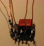
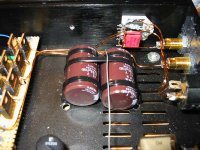
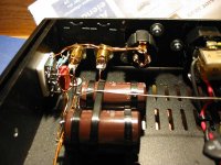
Well, time for new updates... Trafos upped to 24VAC ones = more power and tighter bass, more agile. Coupling cap WIMA MKP10 15nF. Proper wiring. Main filtercaps ELNA LPH 2200uF/63V =midrange more focused/cleaner sound/more dynamic. Ultra matched resistors. DC-offset in uV range 😉
-I can hardly stop listening to it 😀
some pics to follow:
-I can hardly stop listening to it 😀
some pics to follow:
Attachments
Here it is Erik 😉
BTW I have tried dozens of things to my gc, but ended up pretty much where I started.
Hello,
This is the schematic that you made ?
http://www.diyaudio.com/forums/atta...gainclone-pseudo-balanced-input-opa541_22.jpg
Last edited:
- Status
- Not open for further replies.
- Home
- Amplifiers
- Chip Amps
- Gainclone with pseudo-balanced input?