I downloaded the application and it explains it fine. The coupling caps and where to install the 10K "bleeder" resistors. But I have another dumb question.protos said:Just follow the BB application notes.All the DRV134 needs is a good small PS and a couple of bypass caps.You can add the vol pot at the input.+ two output caps.
I must say that I had huge amounts of Dc offset (100mV !)even after the output caps which seemed to drift around over several minutes.This disappeared when I grounded the outputs with a couple of 10k resistors.Can anyone enlighten me?
Anyway I am sorry to say that further listening confirms that this actually blows my Pass Balanced Zen line stage away. In hi-end terms its like going to two classes of pre-amp higher with no compromises that I could detect after a few hours of break in.I even tried it with a battery PS with 4 9V batteries (+- 18V) and it was a killer!
The planned application is using the DRV134 after a pot to be both a buffer and as a single ended to balanced converter. But in the application notes it recommends driving the input with a low impedance source, opamp or buffer.
Did you drive yours with a pot or with an active devise? I think that leving out the active devise is the way to go if the DDRV134 works fine without it. My system is a little different than most here. I use a tube tuner as a source a lot and it needs a high impedance load. I use 125K pots and this is an order of magnitude higher than some used here.
George
As far as I read the DRV134 data sheet, the 10k bleeder is already internal - no need for an additional one.
In my experience installing the 10uF blocking caps didn't help the sound. I have no idea why that should be, and I even used film caps, but it sounded unpleasant. So I live with the DC offset. By data sheet btw the large common mode DC offset is normal, differential should be much smaller, which means the receiver gets rid of it anyway. It works for me, though it gives large turn on and off bumps...
Driving from a high Z likely messes up the balances between those carefully laser trimmed resistors... you then effectively have differet gains in A1, A2 and A3 because you are driving both inverting and non-inverting gain stages with your added Z, affecting them unequally. I would use a simple non-inverting buffer, say OPA 2134. This is what I do.
MBK
A pot at the input worked fine for me although there is some hiss that is just detectable if no music is playing.Perhaps it would be better at the output.Anyway it's such a simple and cheap circuit that you can play around with it as much as you want to get the best combination.
The offset I had was without any input connected and it's true that the differential offset was much smaller but it still was drifting from about 3mv to about 30mv which I think is too high to feed a power amp.MBK said:As far as I read the DRV134 data sheet, the 10k bleeder is already internal - no need for an additional one.
In my experience installing the 10uF blocking caps didn't help the sound. I have no idea why that should be, and I even used film caps, but it sounded unpleasant. So I live with the DC offset. By data sheet btw the large common mode DC offset is normal, differential should be much smaller, which means the receiver gets rid of it anyway. It works for me, though it gives large turn on and off bumps...
Driving from a high Z likely messes up the balances between those carefully laser trimmed resistors... you then effectively have differet gains in A1, A2 and A3 because you are driving both inverting and non-inverting gain stages with your added Z, affecting them unequally. I would use a simple non-inverting buffer, say OPA 2134. This is what I do.
MBK
What specs to look for in a input transformer? At my supplier, Elfa, they only have this transformer http://www.lundahl.se/pdfs/datash/1527_7xl.pdf
I am not 100% clear on the impedances though.
Does the input Z somehow reflect the load Z on the secondaries of the trafo?
In the LL1527 spec sheet it says Input Z=200-900 Ohm (same for Out Z) ? Wouldn't this be a little low for any normal audio pre?
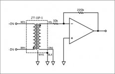
I'm thinking about implementation in a circuit like this:
I am not 100% clear on the impedances though.
Does the input Z somehow reflect the load Z on the secondaries of the trafo?
In the LL1527 spec sheet it says Input Z=200-900 Ohm (same for Out Z) ? Wouldn't this be a little low for any normal audio pre?
I'm thinking about implementation in a circuit like this:
Attachments
Mads K
If you use the transformer as 1:1 your input impedance will be the same 10k as the input of the inverting amp. The low driving impedance probably means low inductance of the primary so your preamp should have low output impedance. Passive volume doesn't seem possible.
cheers
peter
If you use the transformer as 1:1 your input impedance will be the same 10k as the input of the inverting amp. The low driving impedance probably means low inductance of the primary so your preamp should have low output impedance. Passive volume doesn't seem possible.
cheers
peter
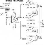
i have just finished my prototype of the following circuit. i have found that even at low volumes, the 4 chips (OPA541) get extremly hot. i do not have them on a heat sink yet, and they are working from +/-15v rails. should they get hot?
i do not have them on a heat sink yet
Don't be so ignorant; Put the chips on heatsinks!!! (And, yes -they should get pretty hot in your arrangement)
Don't be so ignorant; Put the chips on heatsinks!!! (And, yes -they should get pretty hot in your arrangement)
Mad_K said:i do not have them on a heat sink yet
Don't be so ignorant; Put the chips on heatsinks!!! (And, yes -they should get pretty hot in your arrangement)
how could i change my 'arrangement' so that they will not get 'pretty' hot?
Matttcattt
I have no idea at what current do your chips idle and that will probably explain whether they get hot without a heatsink or not.
Have measured the offset of each chip and the differential offset? There doesn't seem to be any means of controlling it in your circuit.
cheers
peter
I have no idea at what current do your chips idle and that will probably explain whether they get hot without a heatsink or not.
Have measured the offset of each chip and the differential offset? There doesn't seem to be any means of controlling it in your circuit.
cheers
peter
I'm also busy with a balanced input gainclone . Without seeing another schematic, I drew up the same schematic as in post #44. Except for one resistor: the 11K resistor from the +input to ground. Simple question, probably difficult answer: what does it do, why is it there?
Regards, Svokke
Regards, Svokke
svokke said:the 11K resistor from the +input to ground. Simple question, probably difficult answer: what does it do, why is it there?
Regards, Svokke
Looks like it's there as a drain after the coupling cap which is mentioned in the post but not in the schematic. If it's supposed to be balanced, the common mode impedances should match between -in and +in. So either both inputs should get a cap and a resistor, or neither.
In my experience I have such little DC offset that I don't use a coupling cap (input is DC free though). I use this schematic, which is practically ready-made for balanced, plus bandwidth limiting:
http://www.linkwitzlab.com/images/graphics/3886amp.gif
how could i change my circuit to:
a. make it better in any way
b. make me able to zero offset.
i have not checked offset, but i will as soon as i have a chance.
a. make it better in any way
b. make me able to zero offset.
i have not checked offset, but i will as soon as i have a chance.
Matttcattt said:how could i change my circuit to:
a. make it better in any way
b. make me able to zero offset.
i have not checked offset, but i will as soon as i have a chance.
a) transformer instead of drv134. local 1uF between V+ and V- on each chip. 1 PSU per channel with 2*4700uF. 300K trimmer on +IN. make the 0,1 Ohm 1% = 0,22-0,47 Ohm 0,1%. use 8 Ohm speakers. put the chips on good sized heatsinks (insulated). better parts. build a nice enclosure (shielded). Correct grounding. Read http://www.diyaudio.com/forums/showthread.php?postid=181855#post181855
etc. etc.
b) 300K trimmer on +IN
Mad_K said:transformer instead of drv134.
what does this change?
local 1uF between V+ and V- on each chip.
what does this do?
1 PSU per channel with 2*4700uF.
im using two 15v regulated supplies (one for each rail) so this is not an option.
300K trimmer on +IN.
will do
make the 0,1 Ohm 1% = 0,22-0,47 Ohm 0,1%.
why higher values?
use 8 Ohm speakers.
i am.
put the chips on good sized heatsinks (insulated).
will do
better parts.
like what, black gate?
 i dont have the money
build a nice enclosure (shielded).
im doing this at the moment
Correct grounding.
i do have
Hi,
To avoid breaking the bank in a good volume pot, one solution could be to use a quad volume control after the drv134. In this way the nasty things introduced by the pot would just be cancelled in the output stage.
A nice way to do this would be to use a chip (volumeclone🙂 ), as they are currently available for home theater applications.
Miguel
Matttcattt said:what does this change?
-the sound
what does this do?
-decouples the supply lines so that your chip doesn't oscillate and such
why higher values?
-to help the chips share the current more equally
like what, black gate?
-you would like low ESR and ESL. check out the ones i specified earlier as an example of a good electrolytic.
[/B]
one solution could be to use a quad volume control
No obvious advantages but a real risk to disbalance the chips. Why use 0.1% resistors if there will be a mismatched pot?
- Status
- Not open for further replies.
- Home
- Amplifiers
- Chip Amps
- Gainclone with pseudo-balanced input?