I did forget to mention a small problem. The transformer hums. The humming seems to oscillate slowly, getting louder then diminishing to nothing and rising again and on and on, it's not loud but loud enough to hear it in the silence of night with music off...I have noticed though that everything in my home hums like that. I suspect it's my dirty apartment power.
When I initially hooked the amp up I had the earth wire from my ac outlet hooked up to the chassis, I got 60Hz hum through my speakers, with it left out it's super silent, I can hear the faintest ssss with my ear a couple of inches away from the whizzer of my Fe206e, the Fostexes are 96db efficient and a barely noticable hiss at full gain is pretty good IMO.
Comments?
Illusus said:what's with the pics? file too big?
well here is another
Wow, I like it !
Thanks for the compliments!
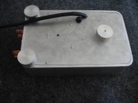
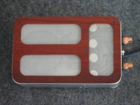
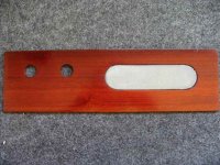
BTW. I built this unit totally DIY guerrila style. The 1/4" al was cut on a table saw, all holes were drilled with a drill press, the holes in the top sub plate were drilled with a forstner bit then the holes connected with a jig saw, same as the wood layer. I did have access to a rather large bender though( my friend is a blacksmith ). The finish, so far, is about eight hours of watching tv or listening to music and scrubbing with scotchbrite pads.
BTW. I built this unit totally DIY guerrila style. The 1/4" al was cut on a table saw, all holes were drilled with a drill press, the holes in the top sub plate were drilled with a forstner bit then the holes connected with a jig saw, same as the wood layer. I did have access to a rather large bender though( my friend is a blacksmith
). The finish, so far, is about eight hours of watching tv or listening to music and scrubbing with scotchbrite pads.karma said:looks great with the wood. last pic is nice wow😉
I designed it to match the face of my DIY'ed Pas pre amp.
Attachments
I put the Illusus pictures on my website:
http://www.briangt.com/gallery/nigc-illusus
I really like the chassis design.
--
Brian
http://www.briangt.com/gallery/nigc-illusus
I really like the chassis design.
--
Brian
Thanks Brian,
Other than the BG caps, you may notice I've used some odd resistors, the nfb and the 680, they are custom made, naked(non-encapsulated) Vishay 102's. I had these laying around for some time and was really excited to put them to use, to me they sound like they posess all the smoothness of the 102 but add the detail those resistors seemed to veil. They even sound smoother and more detailed than the caddock riken combination to me. That is about the only place that I've strayed from convention in the circuit. I should snap a pic of some of those resistors, they are curious little things. I did run this amp on a plank for a month or so, trying as many resistor brand combinations as I could. At first I was slightly sceptical of the claimed differences between components of comparitve quality, but I did have a few different resistors suited for comparison so I went for it. There is a difference, sometimes I switched resistors back and forth to see if that sound I just heard for the first time in a familiar track is the result of a better suited resistor or because I just never strained enough before to hear it. About 75% of the time it was the resistor. Same goes for sustained bass notes, certain combinations made them hang on longer than others.
I'll quit here, this was supposed to be just a "Thanks Brian!"
Just finished gainclone . . .
As I predicted before I started, it does not work.
The right channel does not work for sure. Haven't heard any sound at all actually. But right channel definately doesn't work because when no woofer is attached to the terminal the positive wire that goes from the terminal to the PCB starts to smoke and melt the solder at the point where it solders to the PCB.
When I hook a woofer up to the channel the cap that's closest to where the wire that go to the terminal starts to smoke.
I've been looking at the channel and resoldering things and nothing seems to help. Any one know what the problem might be? Or got ideas for troubleshooting?
Depressing attitude. Sad to hear. A Gainclone is really easy to get going but you can't take shortcuts.Jimmy154 said:As I predicted before I started, it does not work.
My recommendation is to get the datasheet and AN-1192, study those documents, those parts you can understand. Look at the pictures for starters, then compare the offical connection with BrianGT's and Peter Daniels. Get to know the design first, create selfconfidence. Take a deep breath and say: I can do it!
 Then go ahead and study the material which is out, BrianGT's picture directions, very pedagogical, BrianGT.
All caps turned right?
Correct DC supply voltage?
DC voltage connected right?
Grounding OK?
Feedback resistor soldered?
Insulation between LM3875 and the heatsink if you have the "T" type.
Fuses???? Do you have fuses?
Wire diameter? Not too thing?
yes😉 and what works for me if im having problems i like to leave
it for a day and get back at it with clear mind and relaxed. u may find something u didnt see before that may be the problem🙂
it for a day and get back at it with clear mind and relaxed. u may find something u didnt see before that may be the problem🙂
All caps turned right? Yes
Correct DC supply voltage? Don't know what that should be transformer is 22 VAC. Tranformer doesn't have + or - right?
DC voltage connected right? Yes
Grounding OK? Yes
Feedback resistor soldered? My first though was that it was this resistor because I soldered it in the wrong place and then I damaged the casing a little when was desoldering and prying it off the R2 space. But I measured the resistence and it measure the proper resistence.
Insulation between LM3875 and the heatsink if you have the "T" type. No insulation, not that type.
Fuses???? Do you have fuses? 2A slowblo 250 V.
Wire diameter? Not too thing? 18 gauge.
Only only one channel has a problem and both channels look identical. I don't get it but I will try to find the datasheet and AN-1192.
BOM needed
Where would be the most worthwhile place to put money into a GC?
I'm looking at the following as the most expensive pieces (outside of the chassis)
pcb kit (standard vs. premium)
transformer (seemling little choice here)
volume pot
input selector
RCA sets
binding posts
Where would be the most worthwhile place to put money into a GC?
I'm looking at the following as the most expensive pieces (outside of the chassis)
pcb kit (standard vs. premium)
transformer (seemling little choice here)
volume pot
input selector
RCA sets
binding posts
2 A slow, how big is the transformer?Jimmy154 said:Fuses???? Do you have fuses? 2A slowblo 250 V.
If you only have two channels, 2 A will not protect very good. It blows when the power is exceeding 600-800 watts and lasts forever at 450-500 watts!
Peter Daniel said:premium kit and volume pot
peter is there a big sound difference from the basic kit or the premium kit?
or is it the volume pot he sells?
just wondering my friend just ordered 5 basic kits😉
0.82 mm2 if we talk european. That's OK but make this wire glow => 30-50 A!Jimmy154 said:
Wire diameter? Not too thing? 18 gauge.
Tell me you americans: If you just pick up a wire take measure the diameter with something, calipter maybe, how do you know what the AWG number is? For me it seems like mystery this AWG system.
If you know the AWG how do you calculate the resistance? Do you know the diameter<--> AWG by heart? 😕
- Status
- Not open for further replies.
- Home
- Amplifiers
- Chip Amps
- Gainclone building thread based on BrianGT's boards