AWG is tought in the primary schools. You must know it to get 7th grade. This is true for all American schools.
seriously... American Wire Gage is really the standard here. The diameter and cross-section is a very uncommon measurement. As the cross section is stamped on Euro wire, our "gage" is marked on the wire and spool.
Number 0000 wire is 0.4600 inch in diameter. The diameter of each succeeding size is 0.890525 times the diameter of the previous size.
To chose the correct size, find out what size will fit in the hole or fitting. Solder it.
karma said:
peter is there a big sound difference from the basic kit or the premium kit?
or is it the volume pot he sells?
just wondering my friend just ordered 5 basic kits😉
I'm not sure what the difference in sound exactly is, as I never compared those kits. But using better resistors will definitely bring an improvement. The difference will also depend on the rest of your system.
There is no volume pot offered at the moment, but percyaudio.com has a wide selection of different attenuators, including switching types.
Peter Daniel said:
... But using better resistors will definitely bring an improvement. The difference will also depend on the rest of your system.
...
Peter,
What qualities of resistors make them sound better? I know there is a difference because my friend who built a hardwired GC but based it on Brian's board (and your schematic) used Dale 1% resistors initially. They are huge compared to the Phoenix resistors in the basic kit (I don't think they'd even fit the board) but they sound great!
We've been playing with that setup for a couple weeks and have traded the resistors out for three other brands including Caddock and I think the Dale's sound better than all the others except Caddock. I don't think there is a big difference between the Dales and the Caddocks.
Before I built some GCs I honestly didn't know resistors would have such a noticeable impact on sound. Now I'm curious as to why they do!
P-A'S MYSTERY TOUR...
Hi,
All you need is a conversion table:
AWG CONVERTED.
Note also that in the U.K. there also exist SWG standards.
Cheers,😉
Hi,
For me it seems like mystery this AWG system.
All you need is a conversion table:
AWG CONVERTED.
Note also that in the U.K. there also exist SWG standards.
Cheers,😉
Re: P-A'S MYSTERY TOUR...
But what is the advantage to have such a strange unit? Mention one positive thing!
Sorry for threadjacking. Maybe we should start a new thread "AWG is a intelligent way of measuring wire diameter but only P-A doesn't understand it" 😀
Yeah, I know. How do you think I knew 18 AWG was 0.82 mm2? 🙂fdegrove said:Hi,
All you need is a conversion table:
AWG CONVERTED.
Note also that in the U.K. there also exist SWG standards.
Cheers,😉
But what is the advantage to have such a strange unit? Mention one positive thing!
Sorry for threadjacking. Maybe we should start a new thread "AWG is a intelligent way of measuring wire diameter but only P-A doesn't understand it" 😀
I joked earlier that AWG is tought in the primary schools, but it's not far off. Everybody with the slightest electrical experience understands this system. The primary reason is that there is NO OTHER SYSTEM. Starting in the construction (home building) industry, for example, the vanilla icecream is the 12/2 with ground. If you were to order wire with mm2 here, you might just as well speak Martian.
And if you think that's crazy, check out SAE drill sizes... numbers, letters & fractions!
And if you think that's crazy, check out SAE drill sizes... numbers, letters & fractions!
P-A'S MYSTERY TOUR PART II.
Hi,
Who mentioned the word calliper? Right....you did.
No advantage I can think of...
It's just a standard, a convention if you like.
Why do the British drive on the left hand side? Is there any advantage to that?
Ever watched "Clockwise" with John Cleese? Left? Right? Right.
Anyway, over and out.😀
Cheers,😉
Hi,
How do you think I knew 18 AWG was 0.82 mm2?
Who mentioned the word calliper? Right....you did.
But what is the advantage to have such a strange unit? Mention one positive thing!
No advantage I can think of...
It's just a standard, a convention if you like.
Why do the British drive on the left hand side? Is there any advantage to that?
Ever watched "Clockwise" with John Cleese? Left? Right? Right.
Anyway, over and out.😀
Cheers,😉
But what is the advantage to have such a strange unit? Mention one positive thing!
The AWG is an artifact of the wire drawing process. Each gauge is approximately 26% smaller in cross sectional area than the preceeding gauge. The gauge table represents the die line used to reduce a piece of wire to a specific size.
Instead of a wire drawing technician needing to remember exact dimensions (to 3 or 4 decimel places), he only needs to keep track of a simpler gauge number.
widman
Without looking at a chart, which is of course the easiest way, I know that 2 - 18 gauge wires have a mm^2 of 1 - 15. And 2 -15's have mm^2 of 1 - 12 gauge. I know 12 gauge is 2 mm in diameter, 18 gauge most be 1 mm. If you haven't picked up on the patern + 3 AWG is twice the cross-sectional area. All you have to remember is the diameter or area of three gauges. And I also hate the imperial system 😡
I didn't read widman's way, it's better.
I didn't read widman's way, it's better.
What causes a gainclone to hum?
I got my gainclone working, but one of the channels hums a little and the other one hums a lot.
I got my gainclone working, but one of the channels hums a little and the other one hums a lot.
Re: What causes a gainclone to hum?
It doesn't know the words! 😉
Really though in my admittedly limited experience grounding issues are the most common cause of hum. I don't think that proper grounding has been stressed enough (or maybe those more experienced builders assume everyone knows how important it is).
Other causes- bad sources, RF/EMI interference, bad solder joints (quite possibly related to grounding) and noisy components (ie bad capacitor), AC wires too close to input jacks and/or wires (RF/EMI again).
But first suspect grounding problems. Try plugging the amp and the source (CD, tuner whatever) into the same pair of sockets on the wall or better yet into the same outlet strip. That will guarantee polarity is the same. You can also try running a grounding wire from the source to the chassis ground on the amp.
Jimmy154 said:I got my gainclone working, but one of the channels hums a little and the other one hums a lot.
It doesn't know the words! 😉
Really though in my admittedly limited experience grounding issues are the most common cause of hum. I don't think that proper grounding has been stressed enough (or maybe those more experienced builders assume everyone knows how important it is).
Other causes- bad sources, RF/EMI interference, bad solder joints (quite possibly related to grounding) and noisy components (ie bad capacitor), AC wires too close to input jacks and/or wires (RF/EMI again).
But first suspect grounding problems. Try plugging the amp and the source (CD, tuner whatever) into the same pair of sockets on the wall or better yet into the same outlet strip. That will guarantee polarity is the same. You can also try running a grounding wire from the source to the chassis ground on the amp.
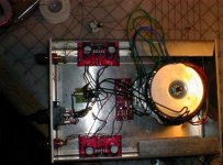
I removed the signal imput wires so I can focus on what's making this humming noise.
I think I might have fired the caps also, I had something wrong with the soldering and/or cleaning of the PCB's and the caps started to smoke and also the power supply and also the soldering joints that go to the terminals and probably other stuff too. So if it's the caps, I don't know if I will ever solve this problem. I don't know if the amp can play music with damaged caps cause it does play music, only with that hum.
I have grounded the plug, and two channels at one point on the bottom of the amp chassis and screwed it down. I don't know what more to do with that. I have resoldered everything and replaced all the wires. All wires are 18 gauge.
The RF/EMI interference I don't know how to fix. Should I use twisted CAT5 network cable wire pairs inside for all the wiring? This would take some time cause there 22 or 24 AWG I would have to use 2 wire pairs for to joints.
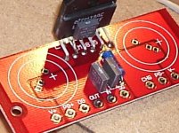
Do you (any one) think that I damaged the caps? The caps didn't start smoking I think it was V+ soldering joint under the cap that was making the smoke.
Here's a picture of it maybe some one can tell what wrong.
I think I might have fired the caps also, I had something wrong with the soldering and/or cleaning of the PCB's and the caps started to smoke and also the power supply and also the soldering joints that go to the terminals and probably other stuff too. So if it's the caps, I don't know if I will ever solve this problem. I don't know if the amp can play music with damaged caps cause it does play music, only with that hum.
I have grounded the plug, and two channels at one point on the bottom of the amp chassis and screwed it down. I don't know what more to do with that. I have resoldered everything and replaced all the wires. All wires are 18 gauge.
The RF/EMI interference I don't know how to fix. Should I use twisted CAT5 network cable wire pairs inside for all the wiring? This would take some time cause there 22 or 24 AWG I would have to use 2 wire pairs for to joints.
Do you (any one) think that I damaged the caps? The caps didn't start smoking I think it was V+ soldering joint under the cap that was making the smoke.
Here's a picture of it maybe some one can tell what wrong.

Thanks for the comments.
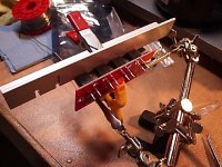
Here is how I line up the rectifiers with scrap material and clamps doing the B_GT bridge board. One clamp to ensure perpendicular to the pcb and one clamp to secure pin depth so that the ironing tip could not move the diodes. This can also allow using two hands to do the soldering.
Chris
Here is how I line up the rectifiers with scrap material and clamps doing the B_GT bridge board. One clamp to ensure perpendicular to the pcb and one clamp to secure pin depth so that the ironing tip could not move the diodes. This can also allow using two hands to do the soldering.
Chris
Attachments
- Status
- Not open for further replies.
- Home
- Amplifiers
- Chip Amps
- Gainclone building thread based on BrianGT's boards