Hans. Just as an aside... and don't know the significance of it.... are you using current mode with Benz LP?
I have a headamp that can switch between Voltage and Current mode, but I prefer the sound of the current mode.Are you using current mode with Benz LP?
It gives a wider and deeper soundstage.
Hans
Are you also using balanced I/O cabling?
What do you suspect the sonics are the result of? Output level differences... greater RF suppression... I/O cable capacitance influences... frequency response differences... to suggest a few?
What do you suspect the sonics are the result of? Output level differences... greater RF suppression... I/O cable capacitance influences... frequency response differences... to suggest a few?
Are you also using balanced I/O cabling?
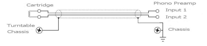
Yes, I'm using balanced cabling, although terminated with RCA plugs and with the screen terminated with separate wires, connecting the TT's chassis to the Head Amp's chassis.
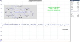
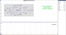
in the attachment the two versions I can switch between, Voltage and Current mode.
Both can be driven Diff In/Diff Out or Diff In/ SE Out by flipping a switch to change the signals to the output.
Power comes from a single 5V 10Watt USB Power Pack that last for many days plying LP's.
Since the Cart's inductance is only in the low uH region, I don't think the cable capacitance can be the cause.
There comes a point in audio where logic explanations don't suffice anymore and you just have to use your ears.
Hans
Attachments
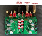

I'm surprised you haven't gone on to use XLR's Hans. It looks like you are using heat shrinking around the differential transistor pairs? Makes sense. I also see lots of capacitors. Are there DC blocking coupling capacitors? By the way, I will be providing SE on the outputs as well.
It is interesting that countless electronic networks can be designed and constructed, yet the sonic outcome can never be necessarily trusted as predictable.
It is interesting that countless electronic networks can be designed and constructed, yet the sonic outcome can never be necessarily trusted as predictable.
Thanks for all contribution!

The square wave on the LP is also very strange. It is recorded with Riaa correction and for some reason it has an uncommon duty cycle.
You are right, I repeated square , this time after my complete preamp and it looks more squerish, nevertheless strange cycle as yours:You should play the square wave with Riaa correction.
My ADC jump around 22kHz was not perfect calibration file I made some time ago. So far did not bother as it is out of range of interest, but now I made good one. This is sweep now, with corrected cal file and after full preamp, including RIAA this time.1) The SPL plot only starts to be valid as from 2Khz.
From there it goes down with 10dB/decade up to 40Khz and not the 50Khz they mention.
So to get a better view on your Cart’s FR, draw a line with a 10dB/dec through the plot starting at 2Khz.
Later today I’ll send you some samples.
However, the one thing I don’t get is why your A/D converter makes this strange jump above 20Khz. Have you any idea why ?
Only god knows why Ortofon did it like this, and did not say a word about it in instructions...
PS, LP that I have is 33 1/3 on both sides, no 45 rpm...?.?
Anyway, now when you explained this 10db/decade fall, it makes sense...
And Ortofon, even after several requests, did not even take the trouble to answer what the supposed goal of this test was.You are right, I repeated square , this time after my complete preamp and it looks more squerish, nevertheless strange cycle as yours:
I will never buy any of their Carts, as good as they may be.
Hans
And the 1kHz THD +N test, now with my preamp including RIAA, still horrible and worst than that.. Actually figures are relative as they dance so much that it is question when I press save button what will come out (note no more peak after 22kHz):

Hi, off subject. I tough that power pack uses single 3.7V LiIon battery cell and than switch mode DC-DC converter to make constant 5V out of it, so even it runs from battery it is SMPS, did you check yours?Power comes from a single 5V 10Watt USB Power Pack that last for many days plying LP's.
Good to see that your ADC is now callibrated correctly.My ADC jump around 22kHz was not perfect calibration file I made some time ago. So far did not bother as it is out of range of interest, but now I made good one. This is sweep now, with corrected cal file and after full preamp, including RIAA this time.
Only god knows why Ortofon did it like this, and did not say a word about it in instructions...
PS, LP that I have is 33 1/3 on both sides, no 45 rpm...?.?
View attachment 1367511
Anyway, now when you explained this 10db/decade fall, it makes sense...
The sweep was recorded in constant velocity, so don’t apply Riaa.
So please show it again how it looks now.
The LP is intented for 33 1/3, but there is no reason why you couldn’t play it at 45rpm.
All frequencies will shift op by a factor 45/(33 1/3) = 1.35
Hans
Good idea !The LP is intented for 33 1/3, but there is no reason why you couldn’t play it at 45rpm.
All frequencies will shift op by a factor 45/(33 1/3) = 1.35
No I did not check this, but as you can see in the ultra low noise spectrum, there are no signs of the usual SMPS anomalies, but you may be right.Hi, off subject. I tough that power pack uses single 3.7V LiIon battery cell and than switch mode DC-DC converter to make constant 5V out of it, so even it runs from battery it is SMPS, did you check yours?
However, the 5V does not feed the head amps directly, but after first filtering a 1.9nV-rtHz regulator on the lower board further flattens the supply voltage individually for the left and the right channel, that´s where you see all the red lytics.
The big advantage of using a power pack however is that there is no intrusion of mains frequency in the supply as shown in the noise spectrum.
Hans
I use one regularly on the go for DAC, or now to power RPI making 3 phase for TT, or to recharge phone.... They are simply good and easy to use.. I'm also not big hater of SMPS, just mentioned for attention.The big advantage of using a power pack however is that there is no intrusion of mains frequency in the supply as shown in the noise spectrum.
Dear Hans, sweep peaks without RIAA
View attachment 1367526
I´m never satisfied, am I 😉
You should not use the octave setting, but straight a frequency setting, just like you did earlier with the noise spectra.
Now you have a 20dB/dec slope instead of 10dB/dec, but this spectrum tells very little.
Hans
It is in spectrum setting... learned that lesson 🙂You should not use the octave setting,
Several reasons, XLR's take more space and even more important, RCA socket's can also receive SE signals from TT's with a fixed cable.I'm surprised you haven't gone on to use XLR's Hans. It looks like you are using heat shrinking around the differential transistor pairs? Makes sense. I also see lots of capacitors. Are there DC blocking coupling capacitors? By the way, I will be providing SE on the outputs as well.
It is interesting that countless electronic networks can be designed and constructed, yet the sonic outcome can never be necessarily trusted as predictable.
What I use is in the attachment.
The Blue caps are in the supply of the individual amps, but everything is DC coupled and servo's keep the inputs within 1mV.
And
Attachments
Why do I see Oct 13 peak on top and 1/48 octave at the bottom when you're not in the octave mode.Repeated on side 2 , which is the "same" as side 1, still the same
View attachment 1367533
And why isn't the slope not at 10dB/oct ?
You must be doing something wrong.
Hans
- Home
- Source & Line
- Analogue Source
- Fully balanced MC phono preamplifier thoughts