So that all what you say is not correct.
The amp has been tested, dummy and as Eva said, it deliver good sound.
The difference is I have no affiliation selling or wanting to profit off audio, nor diy-audio. I have a job. You can keep showing us videos of these victims you sold product to or show us videos of these false disciples of class-d you work with. haha!
Seriously Son,
Do read the paper and other work (I have and still do), it will give tips on many issues you hiding with that supression circuits you using to obfuscate the real issues. (active delays and 555 monostable circuit).
Oh gosh you way to much fun for one weekend 😀😀
Last edited:
Do read the paper it will give tips on many issues you hiding with that supression circuits you using (active delays and 555 monostable circuit).
Oh gosh you way to much fun for one weekend 😀😀
Why need other solution?
It is just perfect. And it is also for OCP delay.
I am also engineer in real work. I dont sell anything.
So that paper is another evidence that you are actually the one who copy and paste! 😀
Last edited:
And you're dreaming with something digital 😀
But never happen 😀
The other stuff is all commonly used blocks, but I added something different.
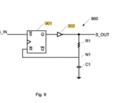
This stage is the "deglitch filter" stage (using basic logic + delay line), it's got some "negligible propagation delay" that needs to be accounted for when designing the compensation network, but... the benefits outweighs the annoyance, as it filters 100% false triggers and acts as a hardware "Noise Gate", blocking "jumpy, high-speed choppy PWM comparator signals", and it works pretty well, PWM signal is always outputting a "clean modulated PWM signal". This will increase the modulator THD quality in general, and avoid the destruction of the output stage if anything like HF rubbish is injected. (I don't think IR chips will block this nor will a discrete front-end block this out) in the event it does the output stage may be destroyed at random.
You can find a clever version of this circuit here.
US8487647B2 - Circuit and method for deglitching an input signal
- Google Patents
In my case, I'm using a TL3016, 7ns propagation delay comparator and even with some hysteresis applied there are still cases recorded on the Ti forum of choppy behaviour under tight layout with decoupled caps and the works. I'm lucky I have access to a 1GHz scope and I see many things during testing.
Most of my energy has been firmware, that was really hard, I spent 8 months getting it right, but now I have a very powerful supervisor circuit, I have removed all protection parts pushed everything into the firmware reduce part count.
I'm still curious how to design a integrator windup clamping circuit, direct that to ADC pin and add a priority order to control what takes over during different overload conditions.
Attachments
Last edited:
Thousands of DIY and Pro Audio Commercial users use Kartino's stable working design - a waste of time to continue discussing with someone who has no working schematics to share, assembled and checked by thousands of users
no youtube videos just blah blah, the spelling of a paid troll from third party
Kartino we live your work and tens of thousands of other DIY and commercial users
Best regards from Germany
no youtube videos just blah blah, the spelling of a paid troll from third party
Kartino we live your work and tens of thousands of other DIY and commercial users
Best regards from Germany
This one has feedforward active error correction implemented !
and working schematic for download or do you not share due commercial
interests?
What is the response time of your short circuit protection?
Dear kanwar,
I have no fancy labs like yours as for not commercialize. Just hobby you know as it woks just fine. I did test directly short-circuited. I did 4 years ago, see below video.
D2KNeo class D Amplifier 2000W 4 ohm overcurrent test - YouTube
Class D killer is mostly not because short circuit but hard clipping which cause core saturated and kill the mosfet. So far we usualy limit clip use DLMS. But I start to develop anti clip. Slow progress as for just my hobby.
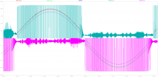
Another my work. Made from PKN H8 concept.
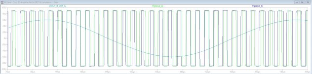
Discontinued, as the output with H8 arrangement is actually equal to only half bridge, because of narrow window time switching.
I am so crazy when think to make full schematic only from the window time concept. But I am happy to know the result is not as I expected.
Discontinued, as the output with H8 arrangement is actually equal to only half bridge, because of narrow window time switching.
I am so crazy when think to make full schematic only from the window time concept. But I am happy to know the result is not as I expected.
Attachments


35 posts so far have been deleted.
@kartino This combative posting style of yours stops now. Failure to heed this will see more severe penalties handed down.
Everyone involved in this also take note. That warning applies to all.

Finally it is decided to say goodbye to this forum after 15+ years
I meet many good people here. I have no plan to come back. Maybe someday but still have no plan.
All the best for all of you.
I don't know if any option to disable my account. So that moderator maybe can help
I meet many good people here. I have no plan to come back. Maybe someday but still have no plan.
All the best for all of you.
I don't know if any option to disable my account. So that moderator maybe can help
Please not go
without you and the FB Group, never I will have knowledge about Class D
without you and the FB Group, never I will have knowledge about Class D
Last edited:
Just ask a moderator, he will help you out😉Finally it is decided to say goodbye to this forum after 15+ years
I meet many good people here. I have no plan to come back. Maybe someday but still have no plan.
All the best for all of you.
I don't know if any option to disable my account. So that moderator maybe can help
- Home
- Amplifiers
- Class D
- Fullbridge D class I could not solve the problem