Thanks also for that input, IT skills are fairly limited, but i eventually managed to achieve some room EQ in my Hypex's using REW so not completely beyond hope and with lots of help on the forum!Personally, I wouldn't go for a MiniDSP solution. With a PC one can use more trickery like mid/side EQ etc. I wouldn't want to be without that sort of tools, plus as much FIR tabs as one would want or need. I know it isn't for everyone, but I like open solutions I can experiment with and learn along the way 🙂.
I shall keep on reading!
Mike
I've mentioned Jriver to you before, the offer still stands to help you with it if you are feeling adventurous 🙂
JR is the last program one should feel intimidated by for a full range line array equalization; multiway is a little bit harder and the full mid-side eq thing that Wesayso does is another level.
Now ABEC and ATH are more of a challenge but it turns out ATH is so well documented that even a software clutch like me could find my way through it.
I was feeling adventurous yesterday and "made" some waveguides with ATH. It has been clear that what my expanding array attempts were missing were a waveguide with the right pattern at center. Now I have the means to design one so I'm going to try my hand it that. Too bad it won't be axi-symmetric. I was getting full spectrum high resolution sims done in under a minute. I'm tempted to order a 16 core Ryzen machine for about a 5x speedup.
Did you catch the latest results from Crumboo?
Vertically, it seems to match quite well with his tweeter-mid-woofer array.
The tweeter shape no doubt helped him achieve that.
Vertically, it seems to match quite well with his tweeter-mid-woofer array.
The tweeter shape no doubt helped him achieve that.
Yes; its quite good vertically. The vertical pattern of the waveguide is key. That is what I'm playing with in ATH. But ATH so far insists on a round throat.
I've mentioned Jriver to you before, the offer still stands to help you with it if you are feeling adventurous 🙂
Greatly appreciate that thought and other inputs thanks, this will be mulled over for a while i expect while i continue to muck around with the LTA and then the Lenco...........
Anyone have views about bothering with analogue and then converting it to digital for processing, will we (I) lose the "magic"?
M
One of my sub amps has DSP and so has to convert analog to digital. No magic issues there because I just use it for LF.
I think you would be fine oversampling (e.g >= 96 khz sampling rate) analog sources with a 32-bit AtoD and DtoA post processing. That might seem overkill but it gives you digital headroom to use digital volume control.
I think you would be fine oversampling (e.g >= 96 khz sampling rate) analog sources with a 32-bit AtoD and DtoA post processing. That might seem overkill but it gives you digital headroom to use digital volume control.
I think you would be fine oversampling (e.g >= 96 khz sampling rate) analog sources with a 32-bit AtoD and DtoA post processing. That might seem overkill but it gives you digital headroom to use digital volume control.
Useful thoughts thankyou, so all in the melting pot for a while now.........
I was able to come up with elliptical waveguides that were good enough to evaluate the concept fairly quickly. The reasons for looking at expanding array with waveguide at center include controlling H directivity to minimize boundary interference from the walls.
For comparison, I'm showing in room response below for my coarse frequency shaded line array (uncontrolled H directivity) with the new expanding array using an elliptical waveguide that is 480mm wide by 272 mm tall
First, the coarse frequency shaded SB65 Line Array
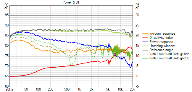
Now the waveguide expanding array
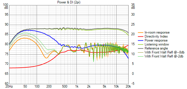
I think that is a worthwhile reduction in sensitivity to the wall!
Note: the ref angle and toe in were chosen so that the reflection point was in front of the baffle; else Vituix would not have included it in the response.
For comparison, I'm showing in room response below for my coarse frequency shaded line array (uncontrolled H directivity) with the new expanding array using an elliptical waveguide that is 480mm wide by 272 mm tall
First, the coarse frequency shaded SB65 Line Array
Now the waveguide expanding array
I think that is a worthwhile reduction in sensitivity to the wall!
Note: the ref angle and toe in were chosen so that the reflection point was in front of the baffle; else Vituix would not have included it in the response.
Attachments


Before going to elliptical waveguide, I simulated with Fluids HF1440 472 mm diameter axisymmetric waveguide and concluded I needed a wg with narrower vertical directivity:
the round wg:
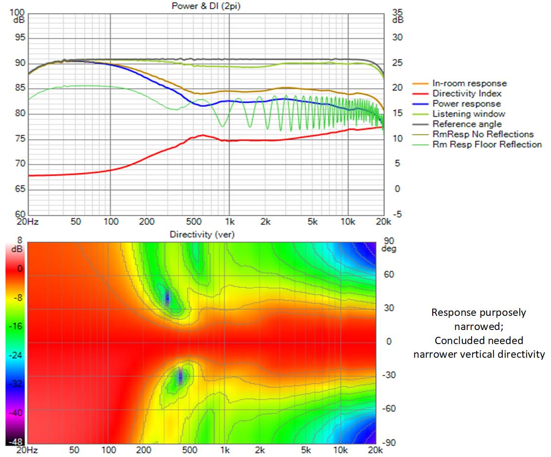
narrowing the vertical response near XO via overlap did improve the floor response but the shape of the vertical polar response is hardly optimal
by contrast, the elliptical wg:
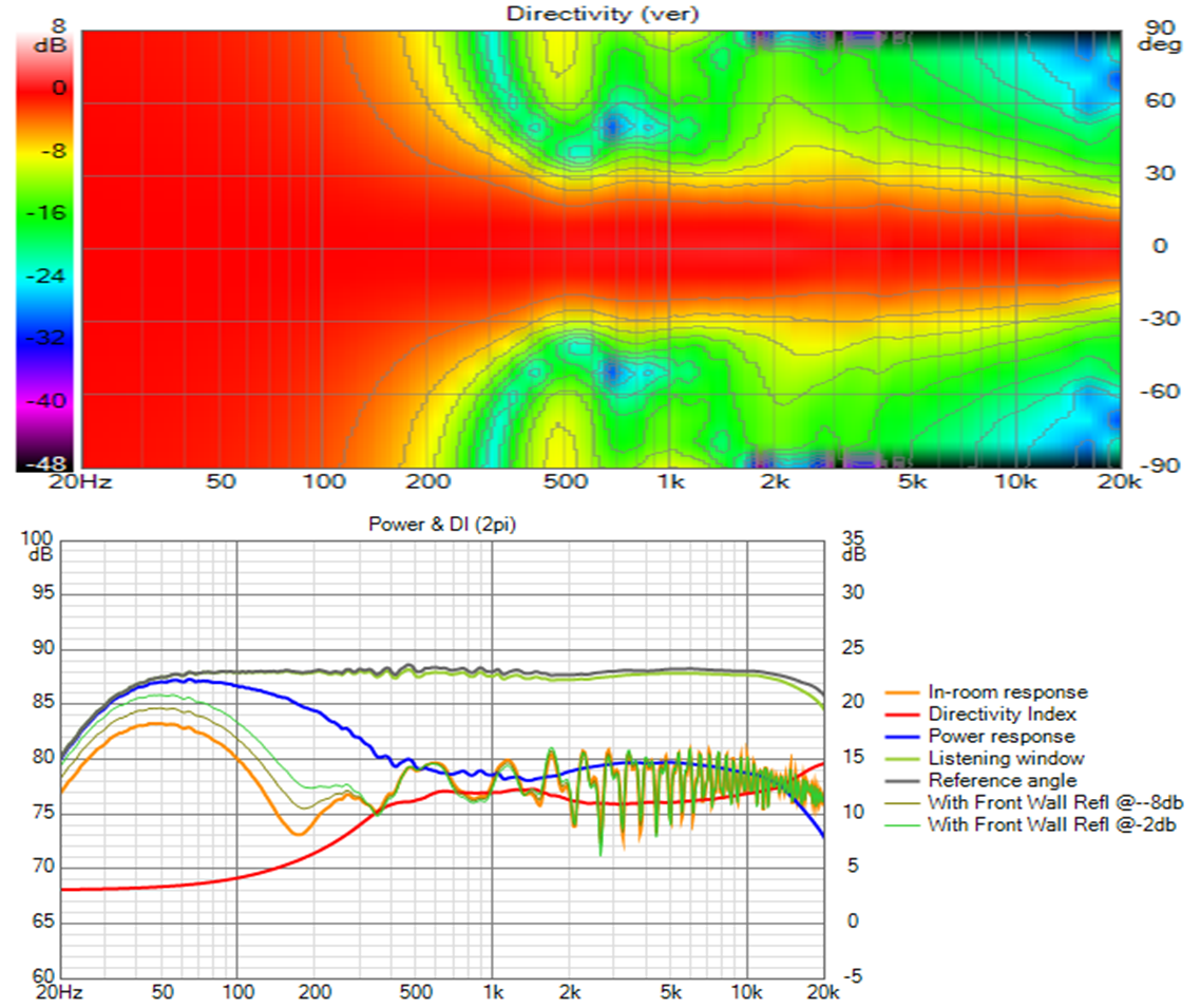
whoops the elliptical had both floor and ceiling. Here are both round and elliptical together each floor only, round on top:
The elliptical is clearly much better. Pattern flip isn't an issue when the asymmetric waveguide is incorporated in an expanding array because the array controls the vertical response (but only down to about 200 Hz because the array as simulated isn't floor to ceiling).
I wonder if I should go even narrower in the vertical..
the round wg:
narrowing the vertical response near XO via overlap did improve the floor response but the shape of the vertical polar response is hardly optimal
by contrast, the elliptical wg:
whoops the elliptical had both floor and ceiling. Here are both round and elliptical together each floor only, round on top:
The elliptical is clearly much better. Pattern flip isn't an issue when the asymmetric waveguide is incorporated in an expanding array because the array controls the vertical response (but only down to about 200 Hz because the array as simulated isn't floor to ceiling).
I wonder if I should go even narrower in the vertical..
Attachments

Last edited:
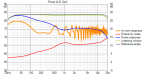
The vertical is a better match and has minimized the lobing at crossover seen before but the DI and power response is now worse. One good thing about the straight array is the rising DI with no real lumps or bumps.The elliptical is clearly much better.
I understand the desire for an even vertical response but I would not prioritize it over the horizontal or overall power response myself.
My "better" was in the sense of the wg's ability to reduce the floor reflection. As it contributes only above its XO of 1200 hz, the big hump in the power response is not due to the waveguide but to the array only having been expanded in two steps. The (elusive) goal is a vertical pattern enough wider than a line arrays to allow standing height response to be good after equalization at seated height.
Is it fair to criticize a corner speaker for its rise in power response in the bass when that rise is doe to corner support? The corner is acting as a bass horn and if one were to measure the power response, the measurement would follow the Vituix room response curve, which would have been equalized flat, and therefor show a flat power response.
Today I took an update of Vituix and my sims are all broken, so I can't look into this further at this time. I have another sim in development of a full midwoofer line array with this waveguide at center which will, I expect, give a more line array like power response.
I don't think you understood what I was pointing out.
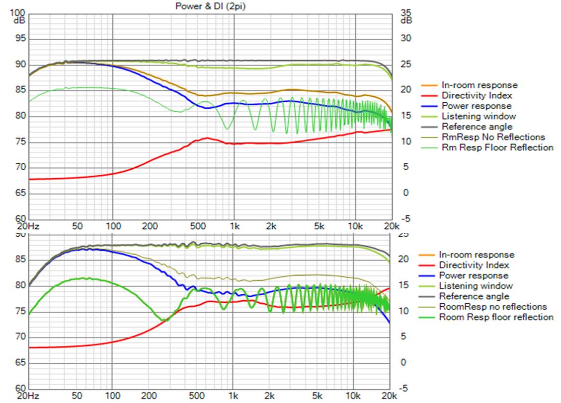
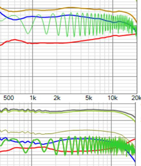
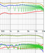
The differences in power and DI are these sections below. In the one with the round guide the power response is generally going down with a couple of dips and maybe a slight rise. This looks pretty good to me apart from the glitch where it doesn't match the array directivity.
In the elliptical one the power response tends to peak through the top of the midrange which I suspect will be audible in a bad way that EQ won't fix. Below 3K the elliptical waveguide is loosing pattern control which is causing a mismatch in the overall power response below that point.
In your coarse shaded array on the page before there is a pretty nice power and DI curve up to about 5K. This is simulated in the corner?
With the waveguided sims both have the same more significant bass rise, this is not what I was talking about but it is interesting now you mention it as the behaviour is different to the shaded array and I am assuming they are all simulated in the same position.
Attachments
You are correct, I didn't understand your point. I was too distracted by that big hump in the power response. I do understand the desire for ideally flat but if not flat then smooth power and DI curves; what I don't have a feel for how much deviation from the ideal is tolerable.
Here is my current state of the art with line array mid bass with a hole for the elliptical waveguide and TC9s
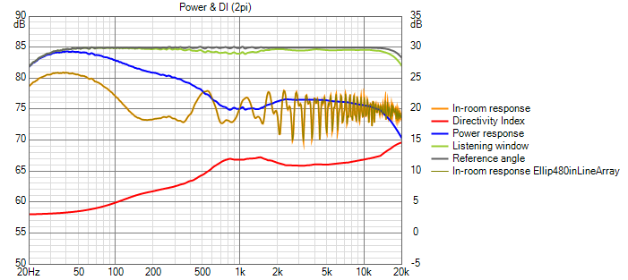
Its got more smoothly rising DI and falling power response with a wide 3db dip around crossover.
Here is my current state of the art with line array mid bass with a hole for the elliptical waveguide and TC9s
Its got more smoothly rising DI and falling power response with a wide 3db dip around crossover.
Attachments

My take from reading research is that dips in the power response are quite benign but peaks are not good. I suspect that smooth is more important than flat for DI and I also suspect that slightly rising DI with a flat on axis response would be preferred. Flat vs rising is something I want to test with different horns.
Further optimization...
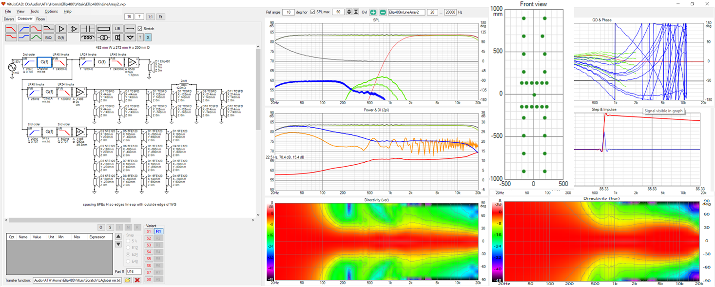
I guess you could call this an expanded array - to the wg + 12 TC9s +16 5FE120s. Its also stretched out to almost 2m tall. The outside edges of the mids and woofers are positioned to line up with the outside edges of the waveguide.
By squeezing the initial 4 TC9s together and adding a shaded pair at the ends of the rows, I was able to take out most of the dip near XO in the H polar map
By playing with overlap range and slopes, I was able to almost completely take out the XO dip in the vertical polar map. Surprisingly, I ended up with an IIR low pass on the 5FE120s, which was a large part of the improvement. Were it not for my philosophy of trying everything when desperate🙂, I would not have found this.
Attachments

Good work! I can se some similarities with my recent sims (in the vertical direction). How wide will be baffle be to accomodate the drivers?
All those 5FE120:s in the low range - what is the reason you don't choose fewer, and bigger, woofers?
All those 5FE120:s in the low range - what is the reason you don't choose fewer, and bigger, woofers?
The baffle will be ~500 mm wide. Using lots of small drivers gave me great control over the directivity.
Two columns vertical provided H directivity down to 500 Hz or so. You would likely need 18" woofers for the same directivity.
The two columns of 5" woofers gave significantly better vertical response than a single 15" at floor level and I wouldn't put a 2nd one up high because of the size and weight and my weak back.
These particular 5" woofers are relatively light and don't need a lot of box volume. In fact, there are enough of them that if you had separate subs you could replace them with TC9s playing 100 Hz up.
That looks better 🙂 I see the reason for the rapid rise in the power response is due to the rapid loss in horizontal control below 500Hz. You might try some drivers bigger than the 5FE's but smaller than 15's on the outer, I think that would blend it better but this speaker has already become quite a monster size. What does the horn look like?Further optimization...
- Home
- Loudspeakers
- Full Range
- Full range line array for wall or corner placement