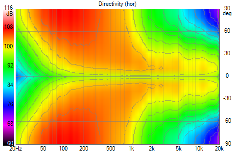
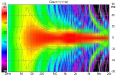
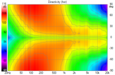
I did some tweaking and got this un-normalized V polar plot for all drivers except the CD. The sidebands are gone but the first pair of rows of 5" drivers are just outside the rim of the waveguide. You have the seeming redundancy of arrays just inside and just outside but that is apparently what it takes to get a sidelobe free pattern
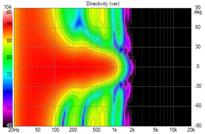
turning on the CD
we see the intentionally narrowed pattern below 1.2 khz
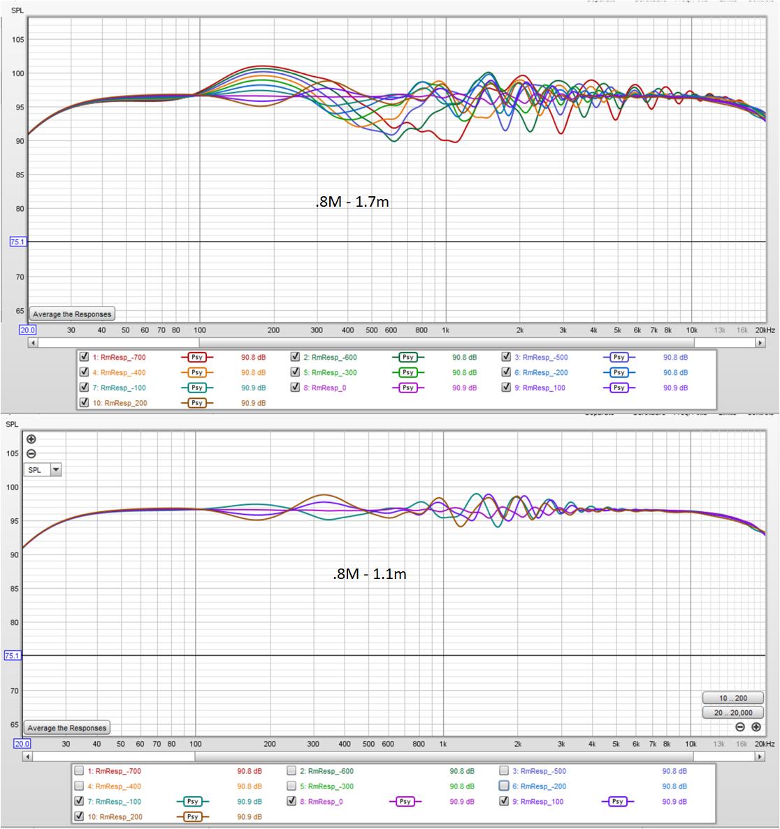
this yields these room responses vs height which are a little better than before, especially as standing height is approached
I think to get better than this above 1 khz a waveguide with a narrower vertical pattern is needed. (perhaps I can extend the narrowed vertical a little higher...)
turning on the CD
we see the intentionally narrowed pattern below 1.2 khz
this yields these room responses vs height which are a little better than before, especially as standing height is approached
I think to get better than this above 1 khz a waveguide with a narrower vertical pattern is needed. (perhaps I can extend the narrowed vertical a little higher...)
Attachments


Last edited:
Is this a 3 or 4 way solution? It looks like plus/minus 2 dB over that 30 cm window.
The horizontal window will be pretty controlled to? Hopefully a less narrowing waist below the horn. Probably less of an issue for you (theoretically speaking) as this is planned to go into a corner, should you be willing build it, right? It's still just an exercise.
For comparison I plotted my array + filters over the same 30 cm, I get a hair over plus/minus 1 dB, but no where near as nice top end behavior. Still impressive for the simplicity of the concept.
(and the minimal use of floor space to get it)

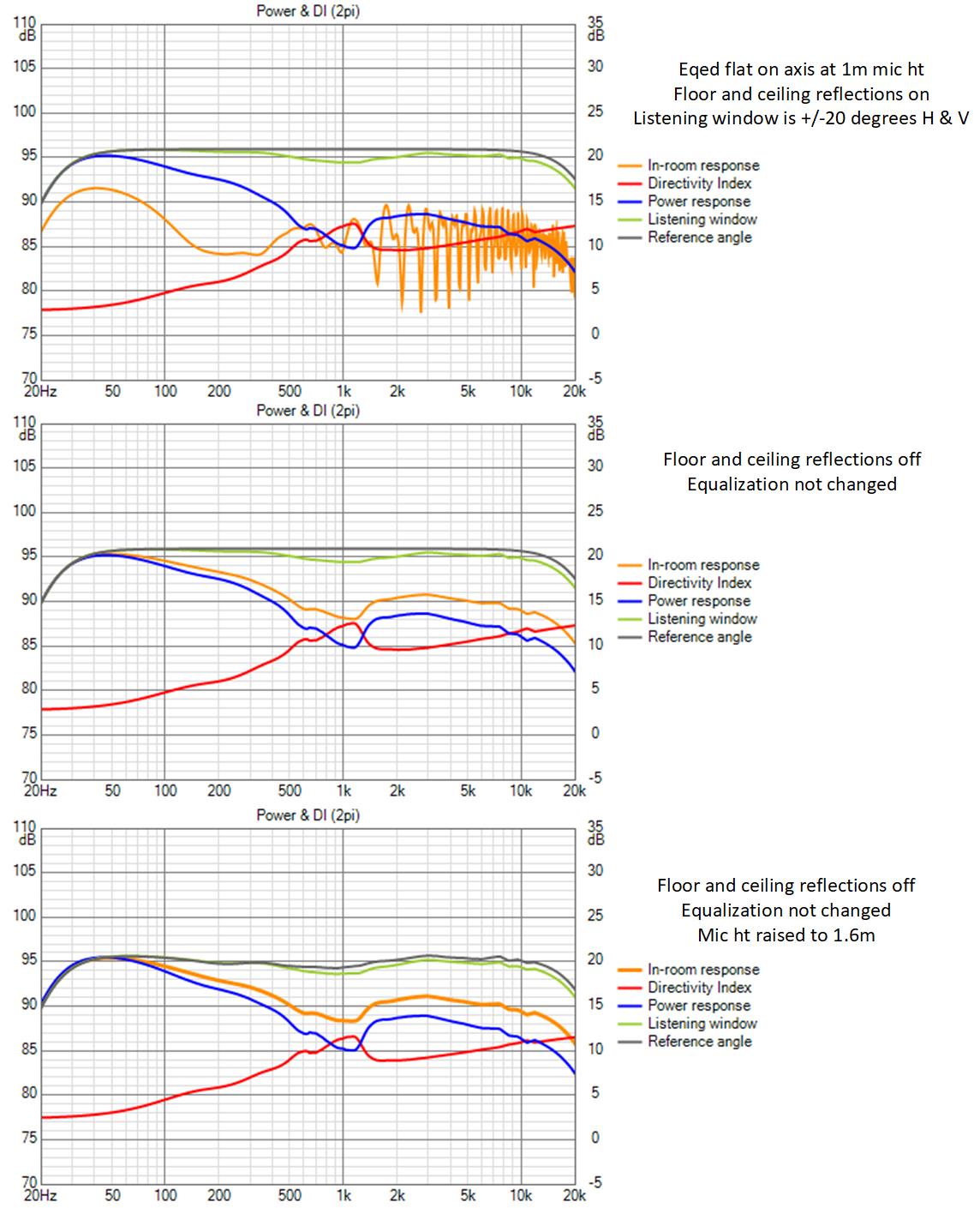
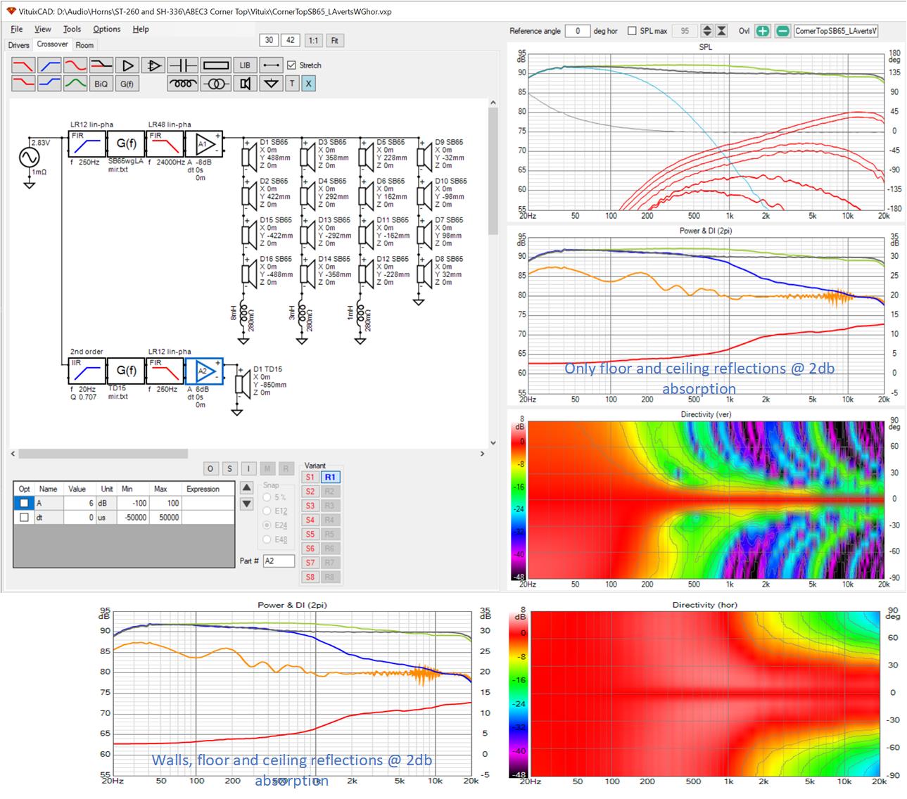
This is with the 2 dB absorption on floor/ceiling and psy smoothing. I did have to re-EQ and used the average of these 4 for a quick fix, but it does make it look better as a bundle 🙂.
The horizontal window will be pretty controlled to? Hopefully a less narrowing waist below the horn. Probably less of an issue for you (theoretically speaking) as this is planned to go into a corner, should you be willing build it, right? It's still just an exercise.
For comparison I plotted my array + filters over the same 30 cm, I get a hair over plus/minus 1 dB, but no where near as nice top end behavior. Still impressive for the simplicity of the concept.
(and the minimal use of floor space to get it)
This is with the 2 dB absorption on floor/ceiling and psy smoothing. I did have to re-EQ and used the average of these 4 for a quick fix, but it does make it look better as a bundle 🙂.
Attachments
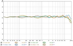
we prize Synergy because its crossovers hold together over the entire pattern window. What we really need mostly is for the crossovers to hold together for at least sitting to standing height variation. I show that here by equalizing with floor and ceiling reflections on, then turning them off, then comparing room response sitting vs standing. I don't see any change
Attachments
For the most part a synergy will act as if it were a single driver. But even single drivers in a room will have variation in it's output depending on in-room position.
But your work here proved that my notion that I've often mentioned, a synergy in an array, is not all that easy to accomplish. Though I still think it would be easier for a synergy that reaches low enough, to actually be part of the low frequency array.
But that would have to be a true synergy with big holes to make it to those low notes.
(disclaimer; I still see your horn with an array of rim drivers within that horn as a variation on the synergy/unity theme 😉, otherwise known as a multiple entry horn)
Yes, what I've done is an MEH and intentionally not a Synergy and its got compelling benefits without needing large holes in the throat, which is what I wanted to see.
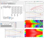
and my latest sims are 4 ways
If the sole criterion is minimal vertical variation, then shaded floor to ceiling line arrays are better. that better high frequency behavior is something you've been interested in; whether it would be preferred in a double blind listening test is another question; one we likely will never answer.
Its certainly would not be easy to build and test the array I just simulated. I would work on simplifying it first myself. I would design a waveguide for a 1" exit (BMS4550) driver since I only need it to play 1 khz up and augment it with only 6 1.5" drivers inside the rim since they only play 500 Hz up. Outside the array I think passively shaded line arrays extending to floor and ceiling (like Crumboo is doing) would be ideal; two columns to control horizontal directivity.
But that is way too much work; I think I'd be satisfied rewiring my arrays for coarse frequency shading. Now that I have somewhat of a handle on abec, I can think about developing a line array horn for horizontal pattern control. It would be nice to have a line array that didn't need padding on the nearby walls.
I actually like the current results from Crumboo even better than the latest 4 way you came up with. Purely based on directivity evenness. I think the tweeter shape helps with the foam plugs to be able to create quite a seamless transition. If one has the big 12" both on top and bottom, a horn in between seems like a small step forward 😀.
A horn array would be a very logical step too. One that has been on and off my mind quite often (lol). I will first finish what I started, and kind of expect my wish list to vanish soon after that... 🙂
A horn array would be a very logical step too. One that has been on and off my mind quite often (lol). I will first finish what I started, and kind of expect my wish list to vanish soon after that... 🙂
Last edited:
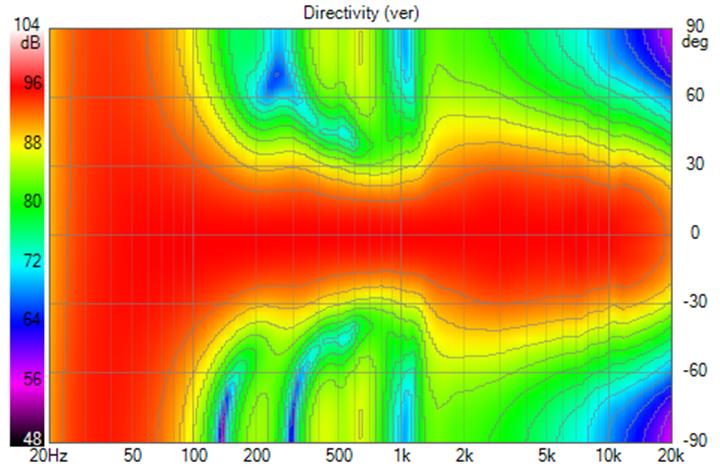
I like Crumboo's results, too. Having said so, i don't like that broadening around 5 khz or the early loss of vertical pattern control - it will have ceiling modes. And I haven't seen the horizontal; which is where a horn or perhaps just a 2nd column of drivers would help
Are you kidding? It is less wide than your horn at 5K, and the directivity index hardly shows a difference...
It is indeed less wide, no doubt because the underlying waveguide has a narrower pattern. Just a few posts earlier today I noted that a waveguide with a narrower vertical pattern would be of benefit to my system.
And it does have a smoother transition between waveguide and array. I had a similarly smooth transition earlier and replaced it with what I now have because I needed a narrower vertical pattern in the transition region (and above).
but it does indeed widen there - to the same 30 degrees which causes sensitivity to floor reflections in my system. that widening is typical of a waveguide starting to lose pattern control, which can be combatted by overlapping it with the narrowing pattern from the driver it is being crossed to.
I've often speculated that if one took the profile of an axisymmetric waveguide and extruded it vertically instead of rotating it around the Z axis, one would get a waveguide with line array vertical directivity and the waveguide's horizontal directivity. Now that I have some (apparently) limited capability to put ABEC simulations together I've been exploring in that direction. But the models get very complex and simulations run longer than overnight so progress so far has been limited. I've concluded I need to strip down to a very simple model and build up from there to validate the idea.
Yesterday it occurred to me that in Vituix, one could combine a vertical directivity file from a line array simulation with a horizontal directivity file from a waveguide simulation and get some idea of the waveguided line array's performance in room. This turned out to be pretty easy to do and has a startling result, which I will get to.
I never noticed before but Vituix can export polar frequency response files, like ABEC/VACS. I equalized a single SB65 and waveguide Vituix sims flat on axis, adjusted them to the same SPL, exported their polar responses. Cut and pasted them into a waveguide-H, line array-V directivity directory and did another Vituix simulation.
This simulation is of a short 4' tall 16 driver array sitting on top of a 15" woofer, with a quick, imperfect passive shading. This waveguide isn't loog enough to eliminate the floor so I'll likely go back to a floor to ceiling array.
Its not surprising that its showing me the horizontal directivity of a waveguide with the vertical directivity of the short line array as those are the input conditions (GIGO). What is surprising is that there is no visible difference between room responses with wall reflections enabled vs disabled - even below the frequency where the waveguide has lost vertical pattern control.
A real line array waveguide with this directivity would be so easy to integrate in a room. I'm anxious to see what ABEC has to say about it but so far ABEC isn't talking.
Attachments
the un-normalized polar map shows about a 3 db dip on axis, which is consistent with the listening window response shape
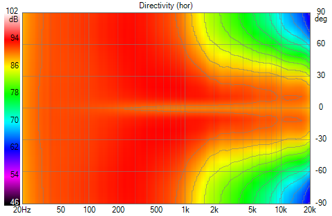
I used fluid's blended108circ waveguide for the horizontal directivity. Interestingly, it doesn't have that dip. Ultimately, I want a rolled back edge waveguide for this purpose.
I used fluid's blended108circ waveguide for the horizontal directivity. Interestingly, it doesn't have that dip. Ultimately, I want a rolled back edge waveguide for this purpose.
Attachments

Here are the un-normalized polars for my full 32 driver floor to ceiling array unnassisted by a woofer, using the waveguide horizontal directivity
the vertical directivity is nicer:
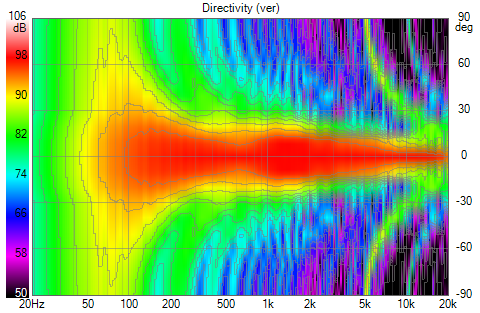
but the on-axis dip is more problematic
Well this is why I do simulations and why Viuix should come before ABEC. No point in doing abec with vituix like this, not without first understanding the dip or making it go away. It could be due to reflection from the unterminated mouth of the waveguide. I can check that...
the vertical directivity is nicer:
but the on-axis dip is more problematic
Well this is why I do simulations and why Viuix should come before ABEC. No point in doing abec with vituix like this, not without first understanding the dip or making it go away. It could be due to reflection from the unterminated mouth of the waveguide. I can check that...
Attachments
Be warned about the back wall's lack of influence, as the ABEC off axis plots may not contain 360 degree data, it will not do anything. I noticed that on my own sims based on ABEC data. But it looks like you have more to worry about.
That is a good point. You have to be careful whether you've generated directivity out to 180 degrees or just 90. These were just 90 because polar map exported directivity is limited to +- 90 degrees
Definitely a problem shown. Whether its a simulation artifact due to cheating on the directivity or to the lack of the baffle the waveguide was intended to work with or to the approach itself is TBD. I think the dip is the same on-axis dip you can get in an axisymmetric waveguide. My abec simulation is of a rolled back edge waveguide which should not have the reflection/diffraction that causes such a dip but that simulation is into its 30th hour and still only indicating 79%
Definitely a problem shown. Whether its a simulation artifact due to cheating on the directivity or to the lack of the baffle the waveguide was intended to work with or to the approach itself is TBD. I think the dip is the same on-axis dip you can get in an axisymmetric waveguide. My abec simulation is of a rolled back edge waveguide which should not have the reflection/diffraction that causes such a dip but that simulation is into its 30th hour and still only indicating 79%
Last edited:
Gents, I am intrigued by these concepts and the incredible detail of your work.
I have had other discussions about arrays as well.
I have little knowledge in this area but the descriptions of the results and the possibility of a totally unobtrusive corner or wall array with great sound appeals.
There is no way i can go into the detail and have the understanding that you do, so, with all your knowledge and experiences how would you advise me.
So a fundamental question.
Is there a reasonable chance to get really appealing domestic sound from a low tech realisation of a non intrusive array, wood (MDF or similar) built cabinets on the wall, possibly corners and no complex additions other than EQ? i know there is a paralell post but I feel it doesn't answer this question.
Or does one have to go much further up the curve to get results that might beat handsomely my current set-up.......
Interested in your thoughts
Mike
I assume by low tech you mean unshaded and minimal DSP equalization. There are a fair number of threads describing low tech arrays and even this thread started out that way. To work well in room, such arrays need absorption at the first reflection points. If you build the arrays into or place them near corners those first reflection points are at the corner wall/baffle intersection and the absorption panels can be thinner because the null frequencies are higher. That is as unobtrusive as it gets ... until this current effort of mine to see if waveguiding the line array, so to speak, does away with the need for this absorption.
I found my unshaded arrays plus subs to be delightful (more than just appealing) but they do require equalization; something as simple as miniDSP 2x4 HD should do it. Higher tech construction - CNC - makes the project so much easier.
Shading only makes them better improving in two ways: reducing/eliminating combing at high frequencies (which arguably isn't problematic without shading) and widening the vertical sweet area.
One thing about corner arrays is they do so good a job of eliminating side wall reflections you might want/need to add an ambience channel. That is one further step up that sophistication ladder but its an optional one. I've been so caught up in these simulations that I have yet to get around to it.
Will an array be better than what you have now? I have no idea. Its really a systems thing - you hear and appreciate the sum of speakers, room, EQ, and treatments. Arrays are not the only solution but done well they are very good.
I haven't learnt much in my audio experimentation, but i enjoy projects and the journey but don't like chucking out equipment that costs (much) money so i am enthusiastic to read first and understand where my enthusiasm might want to take me and then start in a place where i can keep the same base as i start with.There are a fair number of threads describing low tech arrays and even this thread started out that way. ........................Arrays are not the only solution but done well they are very good.
I shall keep an eye on this thread and others and see where that takes me.....
Many thanks for your comprehensive response, best, mike
Personally, I wouldn't go for a MiniDSP solution. With a PC one can use more trickery like mid/side EQ etc. I wouldn't want to be without that sort of tools, plus as much FIR tabs as one would want or need. I know it isn't for everyone, but I like open solutions I can experiment with and learn along the way 🙂.
- Home
- Loudspeakers
- Full Range
- Full range line array for wall or corner placement