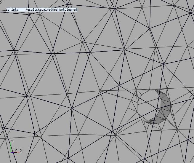
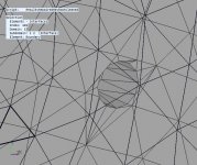
I made those ports by extruding a cylinder through the waveguide surface and cutting on the intersecting surfaces, just as you suggested. but since this was sketchup and the waveguide came from a mesh file instead of from a solid, the result is what you see. each of the three ports of a guadrant are different because the ports intersect the underlying waveguide mesh at different points in its underlying pattern.
If I eliminate the underlying mesh the result isn't as good. Converting from solid surface to STL results in those long skinny triangles that were problematic. Exporting as DAE file and going through MeshLab might work IFF I find the right set of "repairs" to do in MeshLab.
If I eliminate the underlying mesh the result isn't as good. Converting from solid surface to STL results in those long skinny triangles that were problematic. Exporting as DAE file and going through MeshLab might work IFF I find the right set of "repairs" to do in MeshLab.
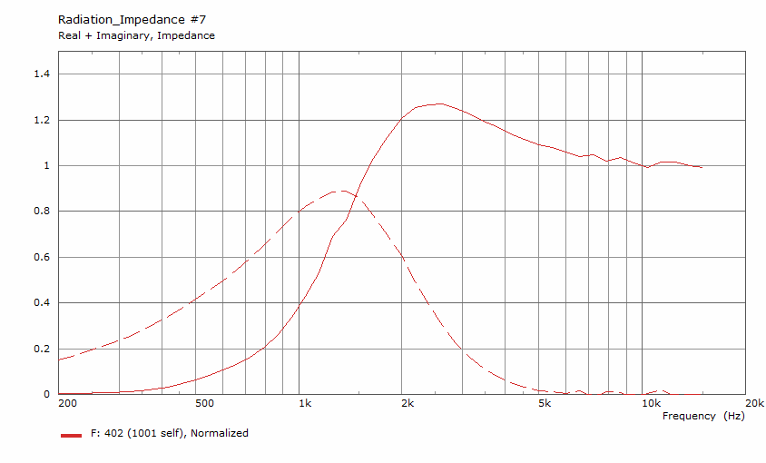
To give the computer something to do overnight, I ran it with NUC=true and 96 frequencies. This only served to accentuate the peak/dip near 1.3 khz
Attachments


I found problems in the exported mesh around one port. this is apparently due to the port coming too close to lines of the intrinsic mesh of the waveguide. I edited the source to remove the intrinsic mesh in the immediate vicinity of the port and started another run,
Attachments

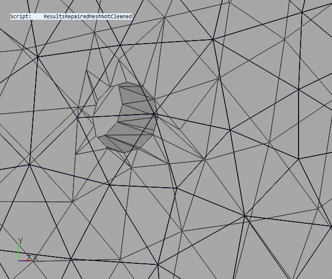
For the record, that mesh still had 2 .6mm gaps around the problem port. The previous iteration had 3 or 4 such gaps so my repairs were partially successful. This run did not have NUC=True
Third times the charm?
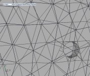
I repaired the repaired mesh = worked directly on the mesh exported by ABEC instead of the source sketchup file and ran it again. This time mesh frequency 2000 and 48 frequencies. no NUC=true
I repaired the repaired mesh = worked directly on the mesh exported by ABEC instead of the source sketchup file and ran it again. This time mesh frequency 2000 and 48 frequencies. no NUC=true
Attachments
Last edited:
reran at mesh freq 4000 and got same results
mesh drawings saved directly from abec
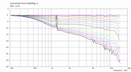
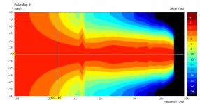
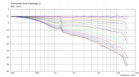
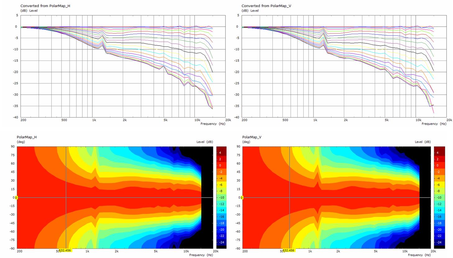
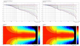
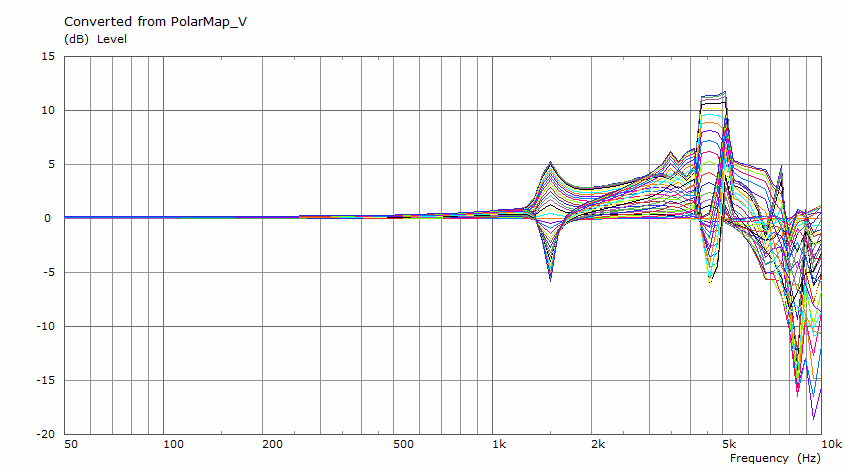
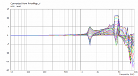
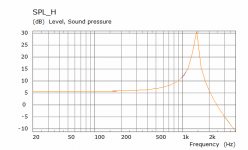
is that off axis peak at 1400 Hz real or a simulation artifact?
if its real, would it be audible?
note: also visible as small change in radiation Z
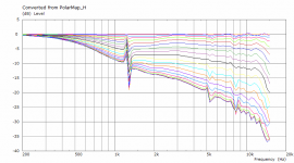
mesh drawings saved directly from abec
is that off axis peak at 1400 Hz real or a simulation artifact?
if its real, would it be audible?
note: also visible as small change in radiation Z
Attachments

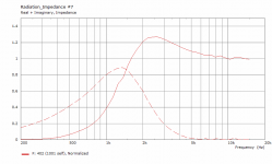
That seems like a simulation artefact to me, it is possible that there is some real disturbance there but it would not be as presented in the simulation.is that off axis peak at 1400 Hz real or a simulation artifact?
if its real, would it be audible?
Sometimes with these issues it is better to look past them and move on as chasing down exactly what the problem is can be very time consuming.
You can see why I said that the CAD and meshing is the biggest challenge when simulating in ABEC 😉
The ports cause a small amount of diffraction but if you were to simulate a finite baffle then they would probably be swamped by the diffraction from a real cabinet. The simulations you and I have run confirm what has been known all along that the bigger the port and the closer it is to the throat the more effect it has on diffraction and polar response.
For larger port areas I think that the PK sound CMI approach with elliptical ports of different sizes with the ports angled away from the waveguide wall angle make a lot of sense.
I can see a coax driver with that sort of port arrangement and one of mabat's OS throat extensions to slip inside the conical CD throat to be worth pursuing.
re'
For larger port areas I think that the PK sound CMI approach with elliptical ports of different sizes with the ports angled away from the waveguide wall angle make a lot of sense.
good luck getting the meshing right for simulating that! but its likely a good way of doing those ports🙂
An array of 12 drivers out on the rim seems extreme compared to just a few larger ones near the throat. Unless the waveguide is very large though, the Synergy will have floor and ceiling reflection issues in room. At the system level, the compelling advantage of the rim array is the extension of the directivity of the waveguide and the ability to integrate that waveguide smoothly into an expanding array, as I've shown in Vituix.
the reason for doing these abec sims, other than learning abec, was to validate those Vituix simulations. That job is only half done. Next I have to investigate the response of the rim array itself and show how to manage the reflection from the mid drivers down into the throat and back.
simulation of a single bandpass chamber
I derived abec input files for the bandpass chamber from the original files. It only takes 30 seconds to run the abec. I export drive element, interface and chamber as separate STL files from my SK source and pull them into abec under separate aliases.
Abec has no trouble with the mesh but that is after I spent time hand meshing the source to control what the stl exporter did.
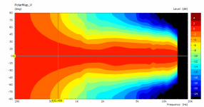
the normalized response shows omnidirectionality well past 800 Hz where it will be low-passed
the un-normalized response
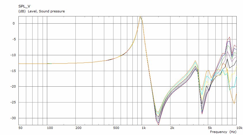
that is the same shape simmed in HR but the peak is at 1 khz instead of 2 khz. Its not quite apples to apples... I've got the port length 3mm longer than it needs to be assuming 10 mm horn wall thickness
This was pretty easy. I should have started with this.
I derived abec input files for the bandpass chamber from the original files. It only takes 30 seconds to run the abec. I export drive element, interface and chamber as separate STL files from my SK source and pull them into abec under separate aliases.
Abec has no trouble with the mesh but that is after I spent time hand meshing the source to control what the stl exporter did.
the normalized response shows omnidirectionality well past 800 Hz where it will be low-passed
the un-normalized response
that is the same shape simmed in HR but the peak is at 1 khz instead of 2 khz. Its not quite apples to apples... I've got the port length 3mm longer than it needs to be assuming 10 mm horn wall thickness
This was pretty easy. I should have started with this.
Attachments

Last edited:
Last edited:
That doesn't look at all correct to me. The blue is an interface which you don't need and the red is the driven element which seems to be only a portion of the port end. The area that is blue should be driven.This was pretty easy. I should have started with this.
Interesting design with something like a conical secondary flare added to an axisymmetric guide. The directivity is lumpy though which is what the latest experiments are trying to improve on.EAW CP621 - they made a kind of coaxial horn design
re' that was easy
when I wrote that I said to myself, "watch out, you are setting yourself up to be corrected by fluid" 🙂
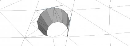
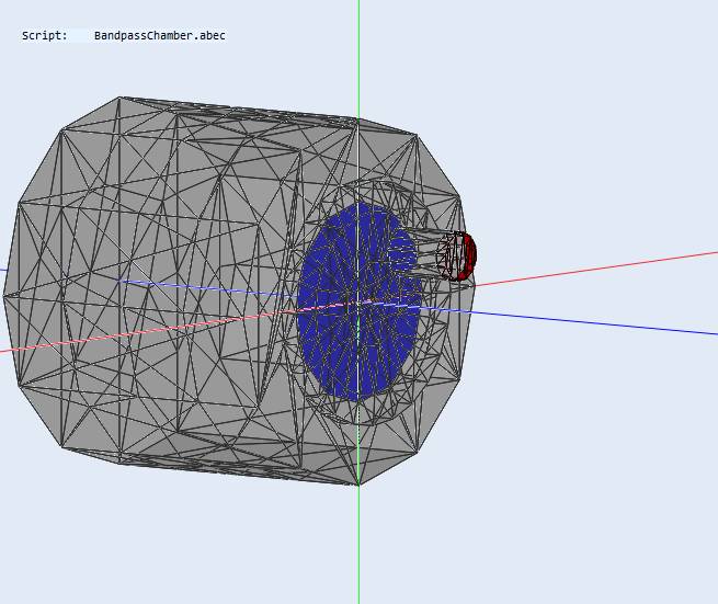
here is the drawing after I loaded the drive element and interface files.
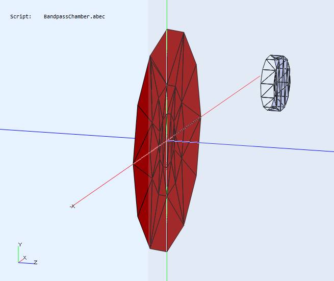
first, I loaded the interface and got the stubby closed end cylinder on the right which will sit at the end of the port when the chamber file is loaded.
then I loaded the drive element file and the red disk appeared. Its area is the same as a DMA45 cone.
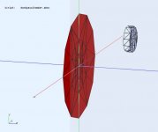
then I load the chamber file and this is what is seen

that is what I intended. (p9ctures captured prior to sim) Colors came out differently this run.
Why don't I need an interface?
when I wrote that I said to myself, "watch out, you are setting yourself up to be corrected by fluid" 🙂
here is the drawing after I loaded the drive element and interface files.
first, I loaded the interface and got the stubby closed end cylinder on the right which will sit at the end of the port when the chamber file is loaded.
then I loaded the drive element file and the red disk appeared. Its area is the same as a DMA45 cone.
then I load the chamber file and this is what is seen
that is what I intended. (p9ctures captured prior to sim) Colors came out differently this run.
Why don't I need an interface?
Attachments
Last edited:
Maybe I wasn't clear. A separate interface wouldn't be needed when the port is inside the horn. When simulating the port and chamber separately it is necessary if an infinite baffle is being used but should only be equivalent to a circle unless the interface extends outside the infinite baffle.
The light blue is an interface that has not been meshed by ABEC yet, it will go darker blue like in the other image afterwards. It should be clear on the side you are looking through
An interface is used to divide subdomains and can be used to separate volumes of air space for the them to be simulated separately. In an infinite baffle simulation there is only really a need for an internal and external subdomain. External is beyond the infinite baffle internal is everything else.
By having part of the port be an interface and not a specific boundary it is like the port ends before the waveguide.
Perhaps what you did is OK but it doesn't seem quite right from the images.
The whole of the port wall and chamber should be grey and the diaphragm red.
If you want me to check it attach the ABEC project as it is easier to see what is happening that way.
Last edited:
I'm simulating one chamber and port by itself, infinite baffle.
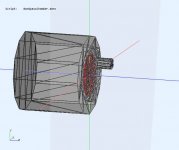
I'll describe the image since the mesh makes it difficult to read.
Most of the chamber simply encloses the back side of the diaphragm/drive element. The front of the drive element sits on a 3mm deep cavity to provide room for the surround roll with some margin. The port is a 10mm long cylinder. that is 8 mm diamener...
I made the interface a stubby cylinder instead of a disk because your interface stands off from the end of the waveguide by 5 mm. No more thought to it than that. I wondered about that, never asked...
The full chamber behind the diaphragm isn't necessary, only to enclose the space in front of it and a baffle surface. The shape of the interface does sometimes make a difference but more so with freespace waveguides. For this I would probably just use a circle at the end of the port.
I'll check when I get home, your explanation sounds reasonable but the first images were weird.
I'll check when I get home, your explanation sounds reasonable but the first images were weird.
I suppose the rear chamber is an unnecessary detail. Since its IB, no sound coming off the back will be "heard". I was really just modelling the cup that will enclose the back of the driver without stopping to realize that the vibrating piston doesn't have a high pass response like a real driver.

- Home
- Loudspeakers
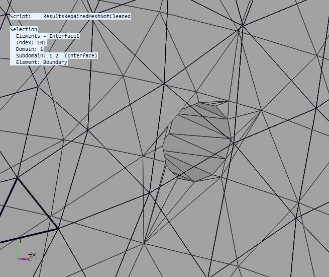
- Full Range
- Full range line array for wall or corner placement