Looks like an ACA Mini (original thread) . Download the two .pdf files attached to post #1 of that thread and read the one called "ACA MINI ARTICLE pt2". Wallah.
Anyone?Perhaps I’ve missed something but is there a place where i can get the correct curves/component values for different drivers Nelson mentioned? I don’t currently have access to a windows machine to run microcap so I tried downloading a similar(?) program for Mac called KiCAD but I can’t get it to open the zipped file so it might not be compatible or I might be doing it wrong
I need it for a pair of FA22rcz - which have been mentioned a couple of times in the thread - in an approx 60L br cabinet if anyone can help. Thanks
Quick question:
To power this EQ circuit, how much 'precision' is recommended, and what types of power circuits are typically most satisfactory?
TIA, Frank
To power this EQ circuit, how much 'precision' is recommended, and what types of power circuits are typically most satisfactory?
TIA, Frank
I used an SMPS power supply, not a wall wart, one that fit in the enclosure along with Mark Johnson's excellent SMPS filter so i could use an IEC cable (limited room on my power strip). I did use 2Sk170's in the signal path of the buffers, I had them in stock.
edit: poor spelling
edit: poor spelling
Last edited:
Thanks! I have a few retired low current linear (LM317) supplies, plus chassis space for a small transformer. If that’s good enough, super. If not, I also have a low current shunted supply but it is bi-polar. I’m running two boards b/c my signal is balanced.
Any other thoughts?
Any other thoughts?
I wasn't sure of the exact values for the low and high filters, so I used pins from an IC socket (I cut the plastic away from the metal pins). I put a cap and resistor in the pins with the correct lead spacing and then solder them to the board. That way I can change filters without desoldering.
I am a newbie here. If I have a PEQ filter generated from REW, can I translate the result to this EQ?
Hello!
I'd like to integrate this nice circuit into my passive preamp in the following topology:
input selector >> eq bypass switch >> eq board >> attenuator >> output
The only thing that gives me pause is that the attenuator in question is a gapped auto-transformer with 150H inductance. I don't know much about filters so I'm wondering if this situation can cause oscillation.
It should be ok i guess, the filter elements of the EQ board are isolated by a buffer and coupling capacitor which isn't different of any other audio component output?
Thanks for any insights.
Auto-transformer attenuator FAQ
Certainly worth a try.
The output impedance of the Jfet is around 100 Ohms or so, and you can get lower with 2SK170 or LSK170.
The output impedance of the Jfet is around 100 Ohms or so, and you can get lower with 2SK170 or LSK170.

Thank you Mr. Pass for your quick reply. Would it be more risky if the filter was put after the attenuator ?

That would put the EQ input's C1/C2 and R2 in parallel with the varying output impedance of the autoformer. Would R2's high resistance dampen any possible oscillation? Sorry if this question seems dump, I'm still learning...
That would put the EQ input's C1/C2 and R2 in parallel with the varying output impedance of the autoformer. Would R2's high resistance dampen any possible oscillation? Sorry if this question seems dump, I'm still learning...
Reflecting on this, the EQ input's C1/C2 and R2 in parallel looks like a snubber of sorts, probably fine as far as oscillation risk is concerned...
If I understand the autoformers' workings correctly its 150H total inductance will reflect at the output as varying from 0 to 37.5H; giving an inductive reactance over 1K ohms for frequencies above 5 Hz.
The first notch would present 9.9H at the output for an inductive reactance over 1K ohms for frequencies above 17 Hz.
Last edited:
I wasn't sure of the exact values for the low and high filters, so I used pins from an IC socket (I cut the plastic away from the metal pins). I put a cap and resistor in the pins with the correct lead spacing and then solder them to the board. That way I can change filters without desoldering.
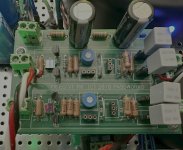
I now have my installation running nicely - and I also went with a plug-n-play implementation for filter capacitors. One board per channel (balanced signal) went right into my new Aleph J that is being made for a 'small' system. I have Lowthers, which might get used with this amp, but I'm also building up some MarkAudio Alpair 12P's in new cabinets. So everything is 'in-progress' with respect to tweaking. The 2-channel linear power supply is tucked under the EQ board and it's quite steady at 24v, so all good there. Last point - notice that I snuck in surface-mount caps at C5. They're Rubycon polymer multilayer type - much smaller than through-hole versions. ...nothing to compare them to sound-wise, but we'll see how the system 'burns-in' and go from there. 👍
View attachment 1358604
Attachments
Last edited:
Perhaps I missed it, but is there a BOM for this? I know the values of many components are user-selectable, but I don't know pitches or voltage ratings.
OK. Thank you elwood625 and, of course, Mr. Pass.
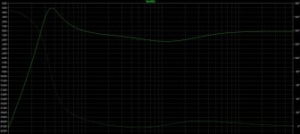
FYI: I ordered the kit and downloaded Micro-Cap and Mr. Pass's model. Here is what I came up with for the Creative Sound Solutions WR-125ST in a sealed cabinet with a Qtc of 0.8:

FYI: I ordered the kit and downloaded Micro-Cap and Mr. Pass's model. Here is what I came up with for the Creative Sound Solutions WR-125ST in a sealed cabinet with a Qtc of 0.8:

Would it be possible to have an idea of the required eq correction for a particular electronics/speaker/room system by spectrum analysis of a reproduced pink noise?
It is easy to generate various types of noise with a computer and there are spectrum analysers and other audio tools available on iphone. Granted that wouldn't match the precision of a proper test equipment but could it get a ballpark approximation to work with?
It is easy to generate various types of noise with a computer and there are spectrum analysers and other audio tools available on iphone. Granted that wouldn't match the precision of a proper test equipment but could it get a ballpark approximation to work with?
Last edited:
I have a spectrum analyzer on my iPad that I’ve messed with and it certainly would not resolve at the level of ~3dB, the kinds of levels for which the Pass EQ board is intended. I’d suggest Room EQ Wizard and a calibrated mic to better and more reproducibly understand what’s going on.
Some advice please! As I'm preparing stuff for BAF weekend after next, I'm putting two FR EQ cards (switchable) onto a multifunction plank. I got their section wired up and hotted, and they powered up fine, but one of the boards has a very dubious Q1 on one side. It's bent, probably from applying too much pressure to achieve the vertical mounting I need. I strongly suspect that one outside leg is detached. An audio check revealed a silent channel. It would be hard to get a useful image, and I see no reason not to replace it.
I have two surplus J113 jfets from some 2022 FE essentials kits and could easily swap one in. Is there much reason for concern here? Since it's is a follower here (as far as I can tell from the schematic), I wouldn't think so. Please warn me off If I'm looking for trouble doing this.
Thanks, Skip
I have two surplus J113 jfets from some 2022 FE essentials kits and could easily swap one in. Is there much reason for concern here? Since it's is a follower here (as far as I can tell from the schematic), I wouldn't think so. Please warn me off If I'm looking for trouble doing this.
Thanks, Skip
- Home
- Amplifiers
- Pass Labs
- Full Range EQ