Pass DIY Addict
Joined 2000
Paid Member
Did some measurements today and discovered one of those amazing and rare times when theory matches practice: my measurements exactly fit the Micro-Cap sim! Awesome sauce! 😎

Hello,
What is the V+ of this circuit ?
2N 3819 is a reasonable substitute for J 113?
thank you
What is the V+ of this circuit ?
2N 3819 is a reasonable substitute for J 113?
thank you
Pass DIY Addict
Joined 2000
Paid Member
Power supply is 24v. RCRC reduces it just a bit. I don't have any input on reasonable substitutions, but the necessary transistors come with the board.
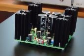
I opted to finish mine "breadboard" style. I added little rubber feet and it will sit behind my preamp.

I opted to finish mine "breadboard" style. I added little rubber feet and it will sit behind my preamp.
Pass DIY Addict
Joined 2000
Paid Member
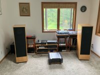
After a few days of listening, these little wonder boards are awesome! I've been using my TangBand 1772 speakers in a 40L vented enclosure for several years. I've been fiddling with an external speaker-level crossover on and off during this time and have made some improvements to the rising top end and the enormous hump from 7-10k, but it never sounded quite right to me. With Nelson's EQ board, I was able to dial things in with much more precision, add a little bass, and now I have a flatter response plot without the nasty 7-10k hump.
This had definitely increased my enjoyment of these speakers! Thank you, Nelson!
This had definitely increased my enjoyment of these speakers! Thank you, Nelson!
Couple of Q's (for any reader)...Power supply is 24v. RCRC reduces it just a bit.
First, the schematic in Nelson's opening post lists supply voltage at 47.5 - I assume that's easily drawn from the plus & minus of a 24v bipolar supply?
Second, I imagine wanting to be able to accommodate different drivers. I have one full-range pair of drivers that definitely shout, and I'm also breaking in some new ones that shouldn't need adjustment to the highs. Is there a simple defeat to the high filter, or would a 'neutral' set of RC parts be best? Many thanks in advance for your suggestions.
The 47.5 are a resistor value (Ohm). the FR EQ runs on +24V single supply.
Last edited:
Has anyone used these with Lii F15's? Was wondering if they would work with the F15 in smaller Caintuck style baffles.
The FullRange EQ is very adaptable if you want/need low range boost and/or mid-to-treble range limitation -- as well expressed in Nelson's article. Lots of this and or that choices. It's cheap and easy to assemble. I think almost everyone would be surprised just trying one without modification even if they have good sized mid-woofers and a fair bit of treble extension from their tweeters all in conventional boxes with decent crossovers. I see help to systems where optimum speaker placement is not possible, bright rooms, and poor recordings of great music, not to mention the more obvious cases. Full Range drivers and open-baffle designs. Sure, they are tone controls, but they are active not passive with those limitations, and crystal clear.
Optimization will need some cap and resistor changes.
Skip
Optimization will need some cap and resistor changes.
Skip
For example, could one simply push the frequency band intended for upper midrange suppression up well above 20kHz? If so, what kind of values for C3 and C4 would accomplish this?Is there a simple defeat to the high filter, or would a 'neutral' set of RC parts be best? Many thanks in advance for your suggestions.
That is mostly a question above my circuitry analysis knowledge level, but the design has fixed filter order built into its design. You can move the center of the boost/cut filters and flatten or increase the amount of the boost/cut. To control the 20khz level much, the center of the cut would have to be fairly high and you might not get what you want in the upper middle range. I would only mislead if I were to guess at ways to mod the design in any change to the circuit architecture.
Skip
Skip
Simple RC lowpass filter calculator says, for C=100pF and R=40k ohms, the -3dB cutoff is 40kHz. That would seem to do it, but for stability issues, etc. I don't have a Windows machine to install Micro-Cap... 🙁For example, could one simply push the frequency band intended for upper midrange suppression up well above 20kHz? If so, what kind of values for C3 and C4 would accomplish this?
Thanks Skip. I’ve not measured them in my room yet, but most the graphs I’ve seen show a big dip at 6.5Khz that probably could use correcting. Of course they drop like a rock after 10K, so some sort of tweeter from 8K up might help as well. There is definitely some potential there.The FullRange EQ is very adaptable if you want/need low range boost and/or mid-to-treble range limitation -- as well expressed in Nelson's article. Lots of this and or that choices. It's cheap and easy to assemble. I think almost everyone would be surprised just trying one without modification even if they have good sized mid-woofers and a fair bit of treble extension from their tweeters all in conventional boxes with decent crossovers. I see help to systems where optimum speaker placement is not possible, bright rooms, and poor recordings of great music, not to mention the more obvious cases. Full Range drivers and open-baffle designs. Sure, they are tone controls, but they are active not passive with those limitations, and crystal clear.
Optimization will need some cap and resistor changes.
Skip
I really look forward to incorporating these boards into my new 'small system' being constructed, and I'm trying to 'guesstimate' some starting values without running a simulator. A small request from those with experience using this circuit. In Nelson's intro to the board he presented the below graph, but the traces were not labeled. Clearly, curve B is C1,2 = 0.1uF, and presumably C3,4 = 1 nF.
First question: Which of the two remaining cap values go with curve A vs curve C?
Second question: The "reference curve" as presented (in Nelson's intro) supposedly used C3,4 = 470pF and its treble minimum was at 4kHz. I believe that's inconsistent with the below graph, in which the lowest C3,4 value was 500pF. If the C3,4 value of 1nF produced curve B with a filter minimum at about 4.6kHz, then aren't these treble curves - with minima from ~2.2kHz to 10kHz - about an octave off? [We see that the frequency shift produced by changing R5+P1 is significant, but could that explain the discrepancy?]
Many thanks for any insights or suggestions!
Frank
Last edited:
The higher values of the capacitors correspond to the lower frequency peaks and dips.
I changed my listening room from the SLOB's to the Lowther Medallian 2 cabinets with PM2A drivers. Threshold FET 10 HL preamp with a EUVL J2 clone amplifier. The Full Range EQ I built to reduce the 7K Lowther "shout". What an improvement, fuller sound, easy to listen to and has the wife's approval!
Thank you Nelson! This project just saved me from buyers remorse with the Lowthers.
Thank you Nelson! This project just saved me from buyers remorse with the Lowthers.
Attachments
1nF, using P1 I was able to adjust the sound, it took a couple of turns before I heard what I was looking for.
Perhaps I’ve missed something but is there a place where i can get the correct curves/component values for different drivers Nelson mentioned? I don’t currently have access to a windows machine to run microcap so I tried downloading a similar(?) program for Mac called KiCAD but I can’t get it to open the zipped file so it might not be compatible or I might be doing it wrong
I need it for a pair of FA22rcz - which have been mentioned a couple of times in the thread - in an approx 60L br cabinet if anyone can help. Thanks
I need it for a pair of FA22rcz - which have been mentioned a couple of times in the thread - in an approx 60L br cabinet if anyone can help. Thanks
Can anybody identify the amp (presumably 5 watt) on top of the speaker in the opening photo?
EDIT: Found it. Amp camp mini amp.
https://diyaudiostore.com/products/aca-mini-bundle
EDIT: Found it. Amp camp mini amp.
https://diyaudiostore.com/products/aca-mini-bundle
Attachments
- Home
- Amplifiers
- Pass Labs
- Full Range EQ