@SomeJoe
yes it works with white noise and Spectroid app on smartfone.
Checked the mic by measuring known loudspeakers.
Found out that some adjustments in Spectroid helps reading the frequency response.
you have to find out where is your mic on your smartfone.
I tested that by tapping at the questioned positions and you detect like this max amplitude where the mic is.
No worries. Worst case is a little offset in what is AC coupled circuit anyway...Some advice please! As I'm preparing stuff for BAF weekend after next, I'm putting two FR EQ cards (switchable) onto a multifunction plank. I got their section wired up and hotted, and they powered up fine, but one of the boards has a very dubious Q1 on one side. It's bent, probably from applying too much pressure to achieve the vertical mounting I need. I strongly suspect that one outside leg is detached. An audio check revealed a silent channel. It would be hard to get a useful image, and I see no reason not to replace it.
I have two surplus J113 jfets from some 2022 FE essentials kits and could easily swap one in. Is there much reason for concern here? Since it's is a follower here (as far as I can tell from the schematic), I wouldn't think so. Please warn me off If I'm looking for trouble doing this.
Thanks, Skip
Thanks for maiking the test, really good to know something can be worked out! I'll certainly check out this app.yes it works with white noise and Spectroid app on smartfone.
On the other hand calibrated mics can be had fairly cheap on Amazon, that would make a very nice "from me to me" christmas gift 😎
Being able to tweak/compensate room accoustics using spectrum analysis is a dream I've had ever since I became interested in hifi in the 80's... Of course for the longest time the gear was too expensive for my budget but cost reductions and advances in technology along with digital signal processing make it possible now... Definetely something I'll get into soon.
For those who use LTSpice maybe this is useful: FR_EQ.asc
Thanks so much for sharing the LTspice configuration for filter parameters. When I open the FR_EQ.asc and try the 'run' button, I get a blank black box as the result. I'm using the latest OSX version freshly installed (for only this purpose). Any suggestions to get the program producing? Many thanks in advance!
Frank
Oh cute! I found the LTspice probe tool and see how it works. For others, hover the probe over the 'out' box and click. 🙂
I'm getting ready to build my Full Range EQ.
Still debating what values I'll use for C1-C4 and R1-R5, to match this with my Open Baffle Lii Song F-15 two way. I'm very pleased with the speaker's top end and believe I've got a good blend with the two drivers but want the bass to have more emphasis. I'll play with the simulation and fine tune the values.
In the meantime, I've read all 17 pages of postings. I've made a preliminary Part List for my own use, but thought I'd share it. Please keep mind that this is just to the baseline build and, as seen by the many postings, DIYers use their skill set and creativity to adjust the build as needed. For example, my build is going in a mahogany box with a plexiglass lid (Optix actually), with high quality RCA jacks loaded in the back. I am planning on using the recommended Wall Wart, but I'll incorporate a DIY Audio SMPS DC filter between the PS and EQ.
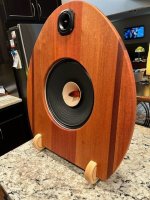
Here is a reference copy of my build list. If anyone sees an error please advise. I've updated it as I read through the postings and don't believe I have any typos, but you should double check it before you use it (just to be sure). Also attached is a pic of my Open Baffle speaker project I'm going to use with the EQ. I have the Iron Preamp that will go with this set. Still deciding on what Power Amp I'll use with this system when everything else is done, I've got several on the shelf but might just build something new.
Still debating what values I'll use for C1-C4 and R1-R5, to match this with my Open Baffle Lii Song F-15 two way. I'm very pleased with the speaker's top end and believe I've got a good blend with the two drivers but want the bass to have more emphasis. I'll play with the simulation and fine tune the values.
In the meantime, I've read all 17 pages of postings. I've made a preliminary Part List for my own use, but thought I'd share it. Please keep mind that this is just to the baseline build and, as seen by the many postings, DIYers use their skill set and creativity to adjust the build as needed. For example, my build is going in a mahogany box with a plexiglass lid (Optix actually), with high quality RCA jacks loaded in the back. I am planning on using the recommended Wall Wart, but I'll incorporate a DIY Audio SMPS DC filter between the PS and EQ.
Here is a reference copy of my build list. If anyone sees an error please advise. I've updated it as I read through the postings and don't believe I have any typos, but you should double check it before you use it (just to be sure). Also attached is a pic of my Open Baffle speaker project I'm going to use with the EQ. I have the Iron Preamp that will go with this set. Still deciding on what Power Amp I'll use with this system when everything else is done, I've got several on the shelf but might just build something new.
Attachments

Will, I found that simply jumping R4 caused an audible compensatory bump in the high frequency spectrum, which was not needed in my application. I haven't yet found the best way to keep response flat above 400Hz. For reasons beyond me, the LTspice predictions I've tried for small HF corrections haven't sounded 'small'. Will appreciate any insights you develop.I'm very pleased with the speaker's top end and believe I've got a good blend with the two drivers but want the bass to have more emphasis. I'll play with the simulation and fine tune the values.
Frank
I tested it out today and got no signal out.
This is my schematic:

and this is my build:

I'm wondering if some of the components which I removed from the simulation actually need to be populated, even though the simulation showed they are not necessary.
This is my schematic:
and this is my build:
I'm wondering if some of the components which I removed from the simulation actually need to be populated, even though the simulation showed they are not necessary.
My equalizer is still not working.
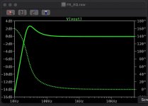
I'm trying to build this without the high-frequency compensation. Here is my modified schematic:

This should give me a +3dB bump at about 50Hz and no high-frequency attenuation. Here is what I measured:

At one point I connected the power supply backwards and one of the 47.5R resistors burst into flames. Might I have damaged something else?
I'm trying to build this without the high-frequency compensation. Here is my modified schematic:
This should give me a +3dB bump at about 50Hz and no high-frequency attenuation. Here is what I measured:
At one point I connected the power supply backwards and one of the 47.5R resistors burst into flames. Might I have damaged something else?
I have no explanation, but am curious what your actual measurement would look like with a smaller R3. Say, 10k? That should boost 50Hz by about 7dB, but will it measurably differ from your measured 35k response curve?
I edited LT Spice to incorporate your schematic values and the attached result is probably what you were expecting as a correction. The 10k graph attached for comparison.
I edited LT Spice to incorporate your schematic values and the attached result is probably what you were expecting as a correction. The 10k graph attached for comparison.
Attachments

Thank you Francolargo. I think an important point is that the response levels off at -13dB. That means there is something very wrong here.
I was thinking that some of the components I didn't install were actually necessary. But if your simulation of my circuit shows that it works, it's either an assembly mistake, or damaged components. I'm going to try replacing the transistors and report back.
I was thinking that some of the components I didn't install were actually necessary. But if your simulation of my circuit shows that it works, it's either an assembly mistake, or damaged components. I'm going to try replacing the transistors and report back.
Coincidently, the phase curve in the simulation does fall at about the same position in the simulation graph as the gain(dB) curve in @Byron's output sweep in his above post with the schematic. I'm curious if that measured output was from a speaker via a microphone (REW?), or perhaps voltage measured from the EQ board itself? I mention this because I am also a bit suspicious that the SPICE simulation doesn't confirm what my filters seem to be doing, and when I have more time (Ha!) I'd like to learn more.
Best,
Frank
Best,
Frank
Last edited:
That measurement was done with an oscilloscope at the OUT terminals on the EQ board. Input was a sine wave at 0.984Vpp centered a 0V. I manually stepped through a range of frequencies and typed the output in to Excel. Then converted to dB and graphed.I'm curious if that measured output was from a speaker via a microphone (REW?), or perhaps voltage measured from the EQ board itself?


Due to a screw up I didn’t order the four 332k metal film resistors for r1 and r2. I found 348k metal films and 330k carbon in my stash. Which would you use or just bite the bullet and order again. Thanks
- Home
- Amplifiers
- Pass Labs
- Full Range EQ