Just completed my Phono stage.
I just completed my passive Phono stage. I used the input stage and passive equalisation components from the Beigebag Software site. The second gain stage is an SRPP. All tubes are ECC83. The sound is very good and I feel like listening to vinyl again.
I had to use a split resistor at the anode of the input stage with a 22uF filter capacitor going to ground , to cut off low frequency garbage coming in from the MOSFET regulated supply. The difference was very audible.
In simulation the SRPP stage has only about 12db supply ripple rejection. I wonder if I would need to filter the supply of the SRPP also. Do (series pass) MOSFET regulators generate low frequency noise ? Looks like a regular RC type filter may be preferable.
I still have hum but can't hear it from my listening position about 8 feet away.
I am rediscovering the sound of vinyl and I like it !
Cheers,
Ashok.
Still, the first pole is formed by the 47nF and series R 100K
Frank
Sorry if i wasn't clear but I simply think this pole is not connected to RIAA at all and the entire correction is done actively. The 100k resistor and output load will still have an effect on the correction but it will only be a second order effect. Please correct me if i'm wrong (very likely i am 🙂)
cheers
peter
Hi Peter,
You're quite correct with your assumption...as said before it all is interdependent.
Ashok,
If anything the FET regulated supply should give you more ripple rejection...not less.
If you want to share the circuit, we could have a closer look.
Cheers,😉
Sorry if i wasn't clear but I simply think this pole is not connected to RIAA at all and the entire correction is done actively. The 100k resistor and output load will still have an effect on the correction but it will only be a second order effect. Please correct me if i'm wrong (very likely i am )
You're quite correct with your assumption...as said before it all is interdependent.
Ashok,
If anything the FET regulated supply should give you more ripple rejection...not less.
If you want to share the circuit, we could have a closer look.
Cheers,😉
My supply.
Hi Fdegrove,
My supply is a two stage unit and I simulated and got a very low ripple on it. But it does not show up low frequency noise. Sounds like a motor running in the distance.
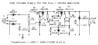
The circuit is attached. I simulated it with two signal generators for the supply and a 100 ohm transformer coil resistance. This drawing just shows a transformer. The 3k3 resistor in the gate of the MOSFET with the 6.8V zener is to protect the MOSFET gate source. Without these the gates get shot everytime I power up and down.
Can you figure out if the circuit is OK or over done ?
thanks,
Ashok.
Hi Fdegrove,
My supply is a two stage unit and I simulated and got a very low ripple on it. But it does not show up low frequency noise. Sounds like a motor running in the distance.
The circuit is attached. I simulated it with two signal generators for the supply and a 100 ohm transformer coil resistance. This drawing just shows a transformer. The 3k3 resistor in the gate of the MOSFET with the 6.8V zener is to protect the MOSFET gate source. Without these the gates get shot everytime I power up and down.
Can you figure out if the circuit is OK or over done ?
thanks,
Ashok.
Attachments
IT MAY COME AS ASHOK...
Hi,
Just kiddin'.
Not being a FET'xpert at all, maybe someone else might enlighten you.
The problem you describe sounds like a minor "motorboating" problem but that's about all I can tell.
Cheers,😉
Hi,
Just kiddin'.
Not being a FET'xpert at all, maybe someone else might enlighten you.
The problem you describe sounds like a minor "motorboating" problem but that's about all I can tell.
Cheers,😉
motorboating
Hi Frank,
I am aware about the motorboating problem. This is not one of them as the signal is much higher in frequency and also contains several other frequencies. The level is very low - you can hear it only if you listen a couple of inches from the speaker. The RC does cut it out.
I will try to check it on a spectrum analyser. A DMM is no use in this case. I should have some time later today. I will put up some pictures also later this morning.
Thanks,
Cheers,
Ashok.
Ashok
If i were you i'd convert the regulator stage to a cap multiplier and see if the problem persists. This may point towards the voltage amp (an 830?!) and maybe a gate stopper will help.
cheers
peter
If i were you i'd convert the regulator stage to a cap multiplier and see if the problem persists. This may point towards the voltage amp (an 830?!) and maybe a gate stopper will help.
cheers
peter
Re: My supply.
I think your circuit needs modification or at least very careful tuning around the actual MOSFET used for Q3. The feedback loop created by R4, R5, and Q3 looks to be very marginal and I wonder if it is workable at all at DC. Depending on the threshold voltage of Q3 (have you measured this?) and the zener current of D3, you might have a circuit which requires Q3 to switch on and off to give you the average voltage you want. I suspect that the noise you are hearing is related to this switching behavior. A simpler, non-feedback circuit, as suggested by Peter/Analog_sa is a good suggestion and one that is much easier to build without careful parts matching.
---Gary
Ashok,My supply is a two stage unit and I simulated and got a very low ripple on it. But it does not show up low frequency noise. Sounds like a motor running in the distance.
Can you figure out if the circuit is OK or over done ?[/B]
I think your circuit needs modification or at least very careful tuning around the actual MOSFET used for Q3. The feedback loop created by R4, R5, and Q3 looks to be very marginal and I wonder if it is workable at all at DC. Depending on the threshold voltage of Q3 (have you measured this?) and the zener current of D3, you might have a circuit which requires Q3 to switch on and off to give you the average voltage you want. I suspect that the noise you are hearing is related to this switching behavior. A simpler, non-feedback circuit, as suggested by Peter/Analog_sa is a good suggestion and one that is much easier to build without careful parts matching.
---Gary
Re: Re: My supply.
As this is only a pre, why not a simply LC, CLC, or CRC input filter, a CCS and glow diode shuntreg?
GaryB said:A simpler, non-feedback circuit, as suggested by Peter/Analog_sa is a good suggestion and one that is much easier to build without careful parts matching.
---Gary
As this is only a pre, why not a simply LC, CLC, or CRC input filter, a CCS and glow diode shuntreg?
My reasons.
That's a good one Frank. But you should have
said " It may come as A shok "!! Great one anyway.
I just realised that many people from the West call
me "A shock " . I think they never realised the other interpretation - even I did not ,till now ...Ha Ha .
Frank and Gary and Brett -
I used the circuit shown ,as I wanted the S/N ratio at 100Hz to be better than -80db by a wide margin. I hate hum artefacts in a Phono stage. With modern opamp stages with decent supplies being 'dead silent' I had to try and cut down supply generated noise. I was aiming for 100Hz ripple to be below 0.1mV. Note that the final SRPP stage that I used has a ripple rejection of
just about -12db.
That's why a capacitance multiplier in the first stage and a regulator in the second stage. Our mains voltage is not stable at all-even by the minute or second ! So regulated it has to be.
I have built many similar regulated stages over the years in SS.
The bottom resistor ( 64K) in the feedback is small. I used 68K and I will look into it again. But I think it is OK as the output DC is quite stable even with a fluctuating incomming voltage. I must check this on a spectrum analyser. Will post results. The noise issue should be clearly visible there. Will try the gate stopper and filter there. Last time I put a cap across the 68K ( 64k in the diagram) the regulator started to oscillate.
Thanks for your feedback. Will get back soon.
cheers.
Ashok.
IT MAY COME AS ASHOK...
That's a good one Frank. But you should have
said " It may come as A shok "!! Great one anyway.
I just realised that many people from the West call
me "A shock " . I think they never realised the other interpretation - even I did not ,till now ...Ha Ha .
Frank and Gary and Brett -
I used the circuit shown ,as I wanted the S/N ratio at 100Hz to be better than -80db by a wide margin. I hate hum artefacts in a Phono stage. With modern opamp stages with decent supplies being 'dead silent' I had to try and cut down supply generated noise. I was aiming for 100Hz ripple to be below 0.1mV. Note that the final SRPP stage that I used has a ripple rejection of
just about -12db.
That's why a capacitance multiplier in the first stage and a regulator in the second stage. Our mains voltage is not stable at all-even by the minute or second ! So regulated it has to be.
I have built many similar regulated stages over the years in SS.
The bottom resistor ( 64K) in the feedback is small. I used 68K and I will look into it again. But I think it is OK as the output DC is quite stable even with a fluctuating incomming voltage. I must check this on a spectrum analyser. Will post results. The noise issue should be clearly visible there. Will try the gate stopper and filter there. Last time I put a cap across the 68K ( 64k in the diagram) the regulator started to oscillate.
Thanks for your feedback. Will get back soon.
cheers.
Ashok.
They're only non-linear high-transconductance VHF valves without heaters
It's just a thought, but what are D4 and D5 doing going directly to the gates of the MOSFETs? I always understood that MOSFETs needed gate-stoppers between their gates and anything else, and that you could not pass go before that was done. I'm probably barking up the wrong tree, but you might like to try it.
It's just a thought, but what are D4 and D5 doing going directly to the gates of the MOSFETs? I always understood that MOSFETs needed gate-stoppers between their gates and anything else, and that you could not pass go before that was done. I'm probably barking up the wrong tree, but you might like to try it.
RIAA PARANOIA...
Hi,
Courtesy of Turner Audio there is a basic reverse RIAA network for those of who like to check the RIAA accurcy of their preamps:
If you like,I can redraw it so it's more easy to read.
Let me know what you think. 😉
REVERSE RIAA.
Hi,
Courtesy of Turner Audio there is a basic reverse RIAA network for those of who like to check the RIAA accurcy of their preamps:
If you like,I can redraw it so it's more easy to read.
Let me know what you think. 😉
REVERSE RIAA.
SH*T RPP.
Hi,
No surprise there, don't count on any SRPP stage to reject ripple.
From a man bigger than me: the SRPP circuit really comes to life when presented by a really well isolated PSU.
Joe Rasmussen are you listening?
Also, keep in mind that not all tubes are good candidates for SRPP use.
So, in the near future expect series regs from me in the 250 to 400V range that you can use with any circuit, including SRPPs.
BTW, look into u follower circuits if PSRR is valuable to you...they still benefit from regulated suplies though.
Cheers,😉
Hi,
In simulation the SRPP stage has only about 12db supply ripple rejection.
No surprise there, don't count on any SRPP stage to reject ripple.
From a man bigger than me: the SRPP circuit really comes to life when presented by a really well isolated PSU.
Joe Rasmussen are you listening?
Also, keep in mind that not all tubes are good candidates for SRPP use.
So, in the near future expect series regs from me in the 250 to 400V range that you can use with any circuit, including SRPPs.
BTW, look into u follower circuits if PSRR is valuable to you...they still benefit from regulated suplies though.
Cheers,😉

Diodes.
Hi EC8010,
These diodes prevent the gate source from breaking down due to excessive voltage. Without it the MOSFET's will breakdown every time you power up and down the circuit. I lost 5 MOSFETS before I realised that I had forgotten the diodes.
Cheers,
Ashok.
Note: There should be one across Drain/Source also. But in this case this diode is built into the device.
It's just a thought, but what are D4 and D5 doing going directly to the gates of the MOSFETs?
Hi EC8010,
These diodes prevent the gate source from breaking down due to excessive voltage. Without it the MOSFET's will breakdown every time you power up and down the circuit. I lost 5 MOSFETS before I realised that I had forgotten the diodes.
Cheers,
Ashok.
Note: There should be one across Drain/Source also. But in this case this diode is built into the device.
I wasn't questioning the necessity of the diode's existence, but I was wondering if they should go directly to the gate.
Direct connection.
Hi EC8010,
I read your earlier post again. Yes you seem to be confused about the "direct connection at the gate".
The gate stopper resistor is to tame the hf response of the device to prevent oscillations. In an application where the tendency to oscillate is reduced , you may not find the resistor. You will however find other resistors in the circuit which will do the same job.
In this case the zener is for protection and keeping it on the side of the resistor as shown will also give the zener some protection. A resistor will prevent any high voltage ( with a low source impedance) from blowing the zener itself. The resistor will limit the current and voltage. If the external resistance is sufficient for this you could avoid using it. In my case I also had hf oscillations and so it does a double job.
cheers.
I know that the resistor is to damp the Q of parasitic oscillations, and that it has to be as close to the gate as possible. I also accept that the resistor protects the Zener. What I am getting at is that having the Zener directly connected to the gate might just be setting up the external resonant circuit that the resistor was intended to damp.
Ok , here is what I think.
Hi EC8010,
I am now going to step into unchartered waters. I have never worked on the exact simulation on this to figure how exactly it works. But I think the resistor in the gate drops the HF gain of the device in conjunction with the input capacitance of the device.
With another device across the gate source we could be only increasing the capacitance and so it will still roll off earlier with the resistor. The values are not "exact" and so will work over a range of values. We are talking about the RF frequency range I assume.
Does this look any better ?
Cheers.
- Home
- Amplifiers
- Tubes / Valves
- Frank's Ultimate Tube Preamp