
There is a relay protection circuit in the amp which is not drawn in the basic schematic. It is adjustable as well and there is a service bulletin from FM on how to set it. I used my 711 amps on a pair of Thiel CS5i's which are a low impedance load and the factory setting would not allow the amp to come out of standby. I had to adjust the variable pot in the protection circuit so when I turned it on it would come out of standby and engage the relay.I am talking about main circuit of fm acoustic power amplifier there is no dc protection how to add dc protection for this amplifier?
I do not have a schematic of the circuit but it does sense the load somehow.
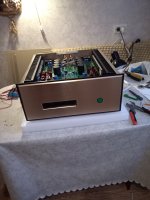
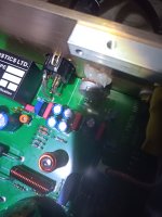
Last month I purchased a completed FM711 clone with upgraded toroidal from the 'SUQIYA Hi Fi Audio Store' (https://www.aliexpress.com/item/1005007235592323.html). Unfortunately it was DOA with only the power button illuminating and the power supply relay triggering but nothing else. A quick inspection showed the reason - three broken output transistors and the trigger circuit voltage regulator (LM7812). Also two screws were floating about loose inside the amp.
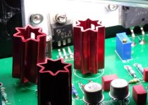
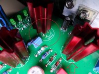
The store sent me replacement parts and now the trigger circuit worked (front display lights up) but still nothing from the amplifier modules. The store then told me they would send another left channel module. While removing the left PCB, I found one of the transistors with red heatsink had two broken pins.
The new left module arrived a few days ago and was fully populated except for the input level pot. Oh, and despite in being well package in soft foam, the LM7812 had broken pins. Fortunately they had sent me two for the previous attempted repair so I fitted it to the new module.
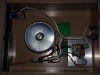
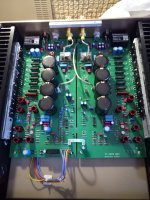
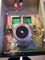
So I fired it up today and it works. However it has a lot of power supply noise coming through the speakers (midrange buzzing). The toroidal wiring looks like a rats nest with three ground wires going to both amp modules so it could be the cause. Has anyone else had this sort of noise issue?
The store sent me replacement parts and now the trigger circuit worked (front display lights up) but still nothing from the amplifier modules. The store then told me they would send another left channel module. While removing the left PCB, I found one of the transistors with red heatsink had two broken pins.
The new left module arrived a few days ago and was fully populated except for the input level pot. Oh, and despite in being well package in soft foam, the LM7812 had broken pins. Fortunately they had sent me two for the previous attempted repair so I fitted it to the new module.
So I fired it up today and it works. However it has a lot of power supply noise coming through the speakers (midrange buzzing). The toroidal wiring looks like a rats nest with three ground wires going to both amp modules so it could be the cause. Has anyone else had this sort of noise issue?
Attachments

Last edited:
If the hum comes from the speakers even without any devices connected to the input, I assume that the reason is in the kind of GND management.
If I have a schematic diagram of only the parts and speaker terminals that are connected to GND and the drawing is also made in the same the way than in real life (i.e. without the GND symbol), I can possibly see the cause.
A friend of me ordered some time ago power amp PCB's (Accuphase E405 clone) - go to
By the first listening test also hum comes from the speakers on both channels. By checking the GND-management I note, that input-GND, NFB-GND, GND of reference CCS, GND of boucherot (zobel) network so as the Loudspeaker-GND runs over the same rail and wire to the capacitor bank of power supply.
By introducing separate cables resp. wires for the loudspeaker terminals and the Boucherot network to the capacitor bank on the power supply, the hum disappeared completely.
If you have an extra power supply for each channel, you should connect the metal enclosure (envelope) to the RCA sockets (not insulated mounting) as the only GND connection between the left and right channel.
P.S.: your pictures show clearly, that the sequence of solder and assembly was exactly the wrong way round. If the leads of the transistors and the voltage regulator had been soldered as the last step after assembly and tightening of the screws, the connecting wires of Transistors would not have broken off.
A better idea would probably be to send all parts separately (as a power amp kit including enclosure parts) so that you can do the assembly yourself.
If I have a schematic diagram of only the parts and speaker terminals that are connected to GND and the drawing is also made in the same the way than in real life (i.e. without the GND symbol), I can possibly see the cause.
A friend of me ordered some time ago power amp PCB's (Accuphase E405 clone) - go to
Accuphase model "E405"-clone and Music Fax Power Amp "F18" and "A-1000" from Kaisaya HiFi Audio - Schematic wanted
For the follow products I am looking for schematic diagrams:
2pcs E405 Gold Seal Tube Post Grade Amplifier Board Class A High Power HIFI AMP Circuit Module 200W MJ15024G/MJ15025G/2SA19-in Amplifier from Consumer Electronics on Aliexpress.com | Alibaba Group
E405 power amplifier board (reference circuit Accuphase) (1 pair) in E405 power amplifier board (reference circuit Accuphase) (1 pair) aus Schalterkappen auf AliExpress.com | Alibaba Group
MJ21195...
- tiefbassuebertr
- Replies: 8
- Forum: Solid State
By the first listening test also hum comes from the speakers on both channels. By checking the GND-management I note, that input-GND, NFB-GND, GND of reference CCS, GND of boucherot (zobel) network so as the Loudspeaker-GND runs over the same rail and wire to the capacitor bank of power supply.
By introducing separate cables resp. wires for the loudspeaker terminals and the Boucherot network to the capacitor bank on the power supply, the hum disappeared completely.
If you have an extra power supply for each channel, you should connect the metal enclosure (envelope) to the RCA sockets (not insulated mounting) as the only GND connection between the left and right channel.
P.S.: your pictures show clearly, that the sequence of solder and assembly was exactly the wrong way round. If the leads of the transistors and the voltage regulator had been soldered as the last step after assembly and tightening of the screws, the connecting wires of Transistors would not have broken off.
A better idea would probably be to send all parts separately (as a power amp kit including enclosure parts) so that you can do the assembly yourself.
Quote: Does it have the noise issue with no device (preamp-Cd etc ) connected or the input shorted? Remember these are a balanced input amp and you have to have the proper adapter as well to use SE inputs. I have seen rca to XLR adapters wired incorrectly.
I am using XLR cables and a source with XLR outputs. While I was fitting the new amp module, I replaced the hot/cold pins to the amps XLR inputs with insulated pins and crossed them over so the phasing would be correct. The buzzing is just noticeable from my listening position 13ft away with a load on the inputs. Switching off my or unplugging my preamp and the volume of the noise increases to (guessing here) 50 to 60db.
I am using XLR cables and a source with XLR outputs. While I was fitting the new amp module, I replaced the hot/cold pins to the amps XLR inputs with insulated pins and crossed them over so the phasing would be correct. The buzzing is just noticeable from my listening position 13ft away with a load on the inputs. Switching off my or unplugging my preamp and the volume of the noise increases to (guessing here) 50 to 60db.
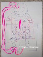
Here is a wiring diagram for the power supply in my buzzing FM711 clone. I would have done away with the 0V link wire and wired the 0V from each bridge rectifier to separate channels but then I don't really know enough about ground loops to know if this is wired correctly.

Hello, I also assembled fm711, but I made it myself from ready-made boards, I already had a transformer with GND pins and the supplier sent me a diagram of how to connect it, there was no hum in the speakers, the only noise is small and can only be heard if you put your ear to the speakers, but the only hum is the transformer itself, but not critical. When first connected, the sound was quiet, then with further warming up it returned to normal, now the sound is fantastic.
Attachments
The legs of the transistor were torn off because the cooling radiators were not screwed to the case. When the case arrived, the radiators were also loose or unscrewed during transportation due to vibration, but I ordered everything separately and assembled it.
I introduced xlr into the amplifier and did not resolder it,Quote: Does it have the noise issue with no device (preamp-Cd etc ) connected or the input shorted? Remember these are a balanced input amp and you have to have the proper adapter as well to use SE inputs. I have seen rca to XLR adapters wired incorrectly.
I am using XLR cables and a source with XLR outputs. While I was fitting the new amp module, I replaced the hot/cold pins to the amps XLR inputs with insulated pins and crossed them over so the phasing would be correct. The buzzing is just noticeable from my listening position 13ft away with a load on the inputs. Switching off my or unplugging my preamp and the volume of the noise increases to (guessing here) 50 to 60db.
I re-soldered the polarity of the RCA - XLR wires, at first I didn’t understand what was wrong, the amplifier barely reproduced the sound, it was almost inaudible, then I figured it out, the problem was in the polarity of the wires and at the input of the XLR amplifier.
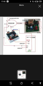
I looked carefully at the wiring shown in this Korean blog (https://blog.naver.com/mrlan64/221425783931) and mine is wired without ground loops. I think the problem is with cable management, all the power supply cables being bunched up and zip-tied together. I am going to rewire the power supply correctly so hopefully that will remove the noise. I also wonder if that 12v transformer is putting noise into the mains.Hello, I also assembled fm711, but I made it myself from ready-made boards, I already had a transformer with GND pins and the supplier sent me a diagram of how to connect it, there was no hum in the speakers, the only noise is small and can only be heard if you put your ear to the speakers, but the only hum is the transformer itself, but not critical. When first connected, the sound was quiet, then with further warming up it returned to normal, now the sound is fantastic.
Does your toroidal have a 12V output in addition to a 50V output? Mine only has 50V ac and no 0V so the bridge rectifiers need to be wired differently.I also wanted to write about a 12 V transformer, I had the same thoughts that because of this transformer.
Yes, I have a 12V output on the troid transformer, when I assembled the amplifier, I did not put a gasket under the transformer, like the link you posted to replace the transformer, but you have a gasket under the transformer for the amplifiers.
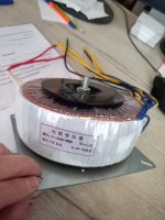

I can add my own 12V winding to the main toroidal:Yes, I have a 12V output on the troid transformer, when I assembled the amplifier, I did not put a gasket under the transformer, like the link you posted to replace the transformer, but you have a gasket under the transformer for the amplifiers.
- Home
- Amplifiers
- Solid State
- FM Acoustics 711 schematic