FM---811---DIY
Attachments

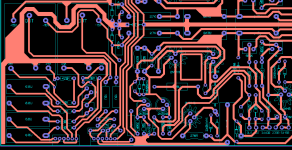
FM-711-PCB
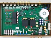
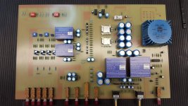
FM-801-PCB
Attachments

Any chance you have any intel on the larger FM 19200 modules that are in the preampsFM-801-PCB
Attachments

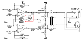
FM-19200 ------ Balanced Line Driver with Floating Output
https://sound-au.com/balance.htm
https://pdf.ic37.com/pdf/download/?id=1517553_24991
https://www.fmacoustics.com/company/heritage/fm-214-fm-216/
http://www.gyraf.dk/schematics/schematics.html
http://www.gyraf.dk/schematics/Neotek_Elite_Bal_Outputs.GIF
http://www.gyraf.dk/schematics/schematics.html
http://audiocircuit.dk/downloads/yamaha/Yamaha-PM1800-mix-sm.pdf
https://elektrotanya.com/ssl_sl4000g_console_sm.pdf/download.html
https://elektrotanya.com/studer_d732_sm.pdf/download.html
Attachments
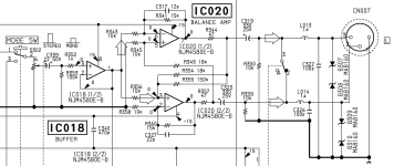

Any chance you have any intel on the larger FM 19200 modules that are in the preamps
Where is the 390 ohm resistor located ?
Attachments
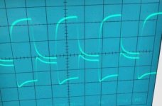
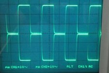
Is there a + - waveform for FM-222 balanced output ???
Attachments
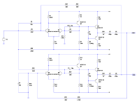
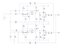
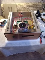
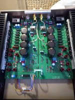
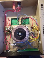
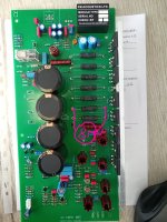
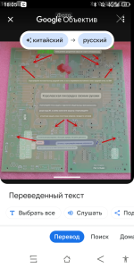
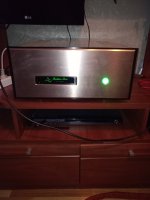
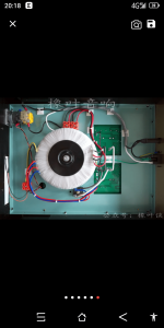
Здравствуйте, собрал усилитель звука из готовых платформ клон FM 711с АлиЭкспресс, всё заработало, звук устраивает, есть непонимание, так как занимаюсь звуком совсем не давно, как говорят некоторые открыли ящик пандоры, непонятно, почему потребление электроэнергии почему-то всего 60Вт при трансформаторе 1000Вт, а в готовых усилителях таких же ,у продавцов в описании написано 120Вт в режиме ожидания и при 30% потреблении 560Вт потребления и ток на выходе продовец пишет выставляется 8МВт это 38мА, не мало это для такого усилителя и такого трансформатора , может это и нормально на плече в этом случае , фото я скидываю, где продовец описывает где и сколько выставлять ток покоя, и ещё кто знает на основной плате выведены три диода, я читал что это показывает какие-то ошибки, можете подсказать какие и как они мигают или просто светятся и в каком порядке.
Hello, I assembled a sound amplifier from ready-made platforms, a clone of FM 711c AliExpress, everything worked, the sound is satisfactory, there is a misunderstanding, since I have been working with sound for a very long time, as some say, I opened Pandora’s box, it is not clear why the electricity consumption is for some reason only 60 W with a 1000 W transformer , and in ready-made amplifiers the same, the sellers in the description write 120W in standby mode and at 30% consumption 560W consumption and the output current, the seller writes, is set to 8MW, which is 38mA, this is not enough for such an amplifier and such a transformer, maybe this is normal for shoulder in this case, I am posting a photo where the seller describes where and how much to set the quiescent current, and who else knows there are three diodes on the main board, I read that this shows some errors, can you tell me which ones and how they blink or just glow and in what order.
 English please.
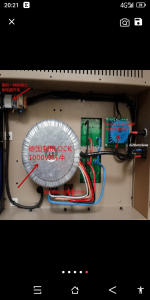
Здравствуйте, собрал усилитель звука из готовых плат клона FM 711, все заработало, звук нормальный, есть недоразумение, так как звуком занимаюсь уже довольно давно, как некоторые говорят открыл ящик Пандоры, это непонятно, почему потребление электроэнергии почему-то всего 60Вт с трансформатором на 1000Вт, а готовые усилители такие же, у продавцов в описании написано 120Вт в режиме ожидания и 30% потребление 560Вт и ток покоя, продавец пишет установлено 8МВт, это 38 мА, это не мало для такого усилителя и такого трансформатора, может на этом плече это нормально, снимаю фото, где продавец говорит проверить ток покоя, попробовал разобраться есть в инете, но там рассматривают только простые усилители на двух транзисторах и тут сложнее, можете посмотреть фото, я тоже снимаю фото схемы, которую нашел в инете не знаю совпадает ли она с плата или нет, продавец схему не снимает
Attachments
-
 IMG_20240113_092615.jpg335.2 KB · Views: 266
 -
 IMG_20240113_093011.jpg406 KB · Views: 247
 -
 IMG_20240113_092610.jpg370.9 KB · Views: 235
 -
 IMG_20231118_115328.jpg322.5 KB · Views: 230
 -
 IMG_20231118_115019.jpg515.2 KB · Views: 242
 -
 Polish_20231202_182958153.jpg454.9 KB · Views: 252
 -
 Screenshot_20231202-180525.png436.9 KB · Views: 239
 -
 1705240751363.jpg214.9 KB · Views: 234
 -
 Screenshot_20231202-180943.png400.1 KB · Views: 247
 -
 Polish_20231123_131447528.jpg245 KB · Views: 267
Please post in English. Further posts will not be approved.
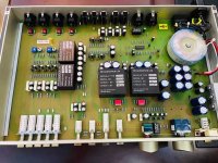
Hello, I assembled a sound amplifier from ready-made FM 711 clone boards, everything worked, the sound is normal, there is a misunderstanding, since I have been dealing with sound for quite a long time, as some say I opened Pandora's box, it is not clear why the electricity consumption for some reason is only 60W with a 1000W transformer, and the finished amplifiers are the same, the sellers have 120W in standby mode and 30% consumption of 560W and rest current, The seller writes 8 MW is installed, it is 38 mA, this is not small for such an amplifier and such a transformer, maybe on this shoulder it is normal, I take a photo where the seller says to check the rest current, I tried to figure it out there on the Internet, but they consider only simple amplifiers on two transistors and here it is more complicated, you can look at the photo, I also take a photo of the circuit that I found on the Internet I do not know whether it coincides with the board or not, The seller does not remove the scheme
I sent it in English, on the page it automatically translates into Russian, now it arrives in English?
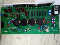
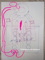
The only thing I see wrong is the hand drawing of the bridge rectifiers. They are not wired in dual mono like the sketch. FM wires them in a ground breaker configuration. Not sure about the translation on the PCB however I have the procedure for setting the protection circuit somewhere for those that have very low Z speakers.I'm sorry, I figured it out, now I'll send messages in English.
If it’s not difficult, can you draw a diagram of how to connect it correctly? I don’t understand the photo of the finished amplifiers, it seems to me that the connection is not the same?
Attachments


- Home
- Amplifiers
- Solid State
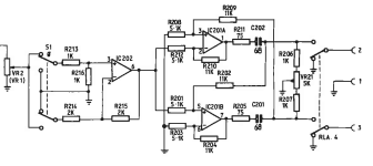
- FM Acoustics 711 schematic