Well, hopefully mine won't beat the FI then... Le/Re ratio >3, yikes! Good thing I didn't wager a new UMIK-1 on my prediction huh...
I just went through your site you have some interesting projects there. You been having fun for sure.
I put that site up in a couple of weeks in 2009 and then lost interest. Just about the only thing that's been added since then was the Large Coil page.
I just found this Dayton imm-6 calibrated measurement mic on sale for $12.25 + shipping at Parts Express. The PDF datasheet shows that sensitivity is slightly less than the old Panasonic module and S/N ratio is A weighted (70 Db), so not quite as good as the Panasonic there either, but I'm thinking it should be good enough to get the data I need for T/S and my LVC issue. Ya think?
Edit: The Dayton mic is calibrated to be flat 18 Hz - 20 kHz. Seems pretty decent for a low buck, no soldering, mic. Along with the $11 USB soundcard maybe those two trinkets will be all I need? I'm fishing for someone to talk me down from the UMIK-1 purchase. $100 buys a lot of OSB and glue!
That Dayton mic is fine but if you want to use it on a cell phone or Android tablet or Apple device you need to find and purchase a measurement app. There are many to choose from but I don't know anything about any of them. Some will be better than others.
If you use it with a Windows device it should be plug and play with any of the free software that runs on windows but without a preamp I'm not sure what sensitivity level it will be. Kind of like taking a capsule and wiring it to a 3.5 mm jack and plugging it into the mic in jack I would guess.
There's also the issue of reflections. Whatever you plug the mic into (cell phone, tablet, computer) is a big piece of hardware that can cause reflection issues but based on the dimensions that shouldn't mess with a subwoofer's passband.
I think I have a short (10 inches maybe) 1/8" jack extension cable that can be used to connect that Dayton mic to the USB soundcard. From there its the USB cable to my laptop. I run windows inside windows (virtual machines on linux, bill gates jailed!) so external USB devices work seamlessly and can be switched on/off between VMs or the host.
I wouldn't mess with a phone and mic for something like this... I have a good custom modded smartphone I built and secured but its not used for apps. Just for calling, texting and WiFi/firewall/Internet access for my laptop out here in the sticks. Anyway, if that mic works on a phone with no preamp gain it should work on the USB soundcard. Soon find out.
I have a domain and website too that I rarely use. Just don't have much to say... its good for putting files and photos up to share with friends and family though. And my own personally managed, private email server is great too. Its worth the money I spend on it just for the email server.
Next week should be fun!
I'm trying to get a handle on optimum response shape for outdoor use. While on this subject I'd like to get a handle on an optimum indoor response as well, particularly the differences in each.
Is this the sort of rising response shape something a person may use for an outdoor sub? If not, how should it be improved for outdoor use? Would it need EQ to flatten it oudoors? Would it be more suitable indoors?

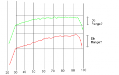
Next is a drawing showing two types of responses:

Note that the green response rises gently until about 45-50 hz then flattens out. The red response continues to rise all the way to the highest frequency. Are either responses useful indoors or outdoors and if so, why?
I assume that the green response may work best in a room with the lower frequencies getting a lift and levelling out the response overall... while the higher frequencies would be less affected by a room. Is that generally a correct assumption?
Is this the sort of rising response shape something a person may use for an outdoor sub? If not, how should it be improved for outdoor use? Would it need EQ to flatten it oudoors? Would it be more suitable indoors?
Next is a drawing showing two types of responses:
Note that the green response rises gently until about 45-50 hz then flattens out. The red response continues to rise all the way to the highest frequency. Are either responses useful indoors or outdoors and if so, why?
I assume that the green response may work best in a room with the lower frequencies getting a lift and levelling out the response overall... while the higher frequencies would be less affected by a room. Is that generally a correct assumption?
Attachments
Outside in the middle of a field there is no room gain, no room modes, no reflections of any kind. So if the subwoofer has a flat response you will measure a flat response in that environment.
In a room things get a lot more tricky. There are reflections everywhere, very strong room modes causing massive peaks and dips in response and below the Shroeder frequency (below the modal region) if the room is stiffly constructed and well sealed you will have room gain. You could have up to 12 db/oct room gain starting at the Shroeder frequency as frequency decreases in a sealed concrete bunker, it's usually a lot less though.
How to estimate any room's gain profile? Impossible. You can make assumptions but it will be pretty useless in practical terms, once you measure any given room it's just a huge mess.
You can use a simple sealed subwoofer with known anechoic or 2 pi response curve to actually measure a room's gain profile, but it will measure differently at different points in the room.
Ideally for a built in subwoofer that won't ever move and for a given listening position that won't ever move, you can measure the room and make the subwoofer's frequency response the inverse of the room gain curve so that they sum to flat. But if it's a sub that isn't built in and will be used in multiple locations all you can do is design for a happy medium.
Take a look at this data-bass article on room gain. See the massive room mode spikes and dips and the room gain? It's all there but it's all but impossible to predict. You have to measure it.
Data-Bass
So for outside use if the sub has a flat response it will measure flat when measured outside. But in room all bets are off, the response is wild and unpredictable and response will change between different rooms and even in different spots in the same room.
An externally hosted image should be here but it was not working when we last tested it.
That pic from the data-bass article says a lot. The black trace is an outside measurement of a sealed sub. The other trace is the in room measurement of the same sub taken at the listening position. The DIFFERENCE between the two traces is the measured room gain profile. There's 30 db of gain at 4 hz and 0 db of gain at 20 hz and wild fluctuations everywhere. At a lot of frequencies it's a negative gain.
And it's a mess. Not at all what you might expect from simplifications like assumptions of 12 db/oct room gain below the modal region and room modes predicted based on room dimensions. It's just a huge mess and there's no way to predict it.
And it will measure different in the same room if you move the sub OR the mic location or both. And it will measure completely different in different rooms.
I have a friend with an old Klipschorn. In his basement the sub sounds good, but upstairs in a room its junk. He has to run a fill-in sub upstairs just to hear the entire frequency range. Its a mess as you said it could be.
So, for the outdoors if I build a sub for flat response, it should play flat. Indoors a gently rising response on the low end may be optimal (dependent) on the gain the room provides. Indoors its a crap-shoot what you get.
Thanks,
So, for the outdoors if I build a sub for flat response, it should play flat. Indoors a gently rising response on the low end may be optimal (dependent) on the gain the room provides. Indoors its a crap-shoot what you get.
Thanks,
Great information just a guy! I just bookmarked your links to build my own speaker tester for REW. I remember you posting the large voicecoil adustments for HR.
It was a very simple impedance jig to make. My resistor measures 1 ohm under the rating and after all was soldered together and heatshrink tubed, the jig measures 3 ohms higher than the resistor measured. So, I made a label with the exact resistance of the jig (cables included) for LIMP.
An update... yes, still hanging in there.
After seeing my initial solder and shrink tube job in action, I built a nicer impedance jig and put it in a project box with separate calibration switches for both LIMP and REW.
I also received the cheap USB sound card from the chinese fleebay seller in Cali (delivered by dogsled and pony apparently) after a long wait. It works pretty good for the price. The Headphone Out jack on it drives the LIMP jig to Line In jack pretty hard and calibrates within 0.13Db. Thats all it needs to do so for less than $11 it looks like it was a good buy.
LIMP (and all of the ARTA software) look to be very useful and easy to learn so far. REW looks like most other crappy java apps, so I haven't played with it at all yet. I may be getting into REW soon though.
I've run into problems getting TSPs from LIMP. Its been ridiculously difficult so far, as the Arta software is very unstable on Windows XP Pro 32 bit and Windows 7 Pro 64 bit. I can't get a SINE measurement at all because LIMP freezes up before getting to 70 Hz in each test. I have to force kill it and start over each time it freezes. The Pink noise measurements work in LIMP, but are not believable at all and not repeatable within a respectable range of error. I may as well be throwing darts at a target, its that bad.
I wondered if using Windows in a (VM) window from my Linux OS was causing problems. I have a spare hard drive for my laptop, so I wiped it and did a fresh install of Win 7 pro 64 bit. That didn't help the problems either. LIMP still freezes up shortly into a sine measurement. Pink noise measurements are still the same junk too.
So now I am left with trying different resistors in the impedance box and hoping that I can get believable TSP measurements after that experiment. I ordered a few different values (1% tolerance) that I don't have in my stock, so in a couple days I'll swap out and see if things improve. If not, then I'll probably just move on up to a DATS V2 purchase.
Meanwhile, my trusty old Fluke 177 digital multimeter died last week. Looks to be a terminal death after many years of being an awesome meter. I hoped it was just the LCD connector after checking everything out, but no luck. So adding injury to my LIMP insults, now I gotta buy another 177. I have a cheap chinese made DMM that I keep around for field work, but its not accurate at all, so the new 177 purchase gotta happen right now. This little horn project won't be ending anytime soon.
Attached is a text file of the last 5 TSP measurements I took of my driver using the PINK noise test in LIMP... if ya wanna see the junk I'm dealing with.
Attachments
From what I understand, LIMP measures the impedance curve and then applies an algorithm or some type of mathematical hocus pocus to derive the t/s parameters from the curve. So as long as the curves look similar things are ok. You can overlay a few curves and see if they are pretty much the same or not.
You will never get the same set of t/s parameters twice. This worried me a bit in the beginning. But if you take your 4 sets of t/s parameters and sim them all in the same box (your horn) are the results that much different? If they are there is a problem. If they are pretty similar then pick a set of parameters that are average and use that.
Your fs is consistently 10 hz higher than published spec. Did you give the driver a good workout before measuring? If it's been sitting for 16 years it will need a good break in with heavy excursion at least to xmax for at least a few minutes. Some people do this in different ways. Some move the cone by hand to stretch it to the limits, some run a sine wave through it at a frequency where the cone will move a lot but it won't draw a lot of power. Some people will run it like that for 24 hours or more but be careful not to overheat the voice coil.
Some of your parameters like qts and qes look pretty stable, they don't change much in your 4 sweeps. Some like Vas and Mms look pretty different, this is normal. As I said you won't ever get the same set of specs twice. It would be nice if they were a bit more consistent but see what you can do with it.
WT2 and DATS (WT2 is better) will probably give more consistent results from sweep to sweep but as long as you can run a bunch of sweeps, sim the results and have them give the same frequency response in the same box you probably don't need to spend the extra money. All my horn designs to date have been based on LIMP measured t/s parameters and they have all turned out pretty close to simulated results despite never getting the same set of t/s parameters twice - in fact I had some pretty large variations between sweeps.
Make sure the driver is consistently in the same position for each sweep - if you measure horizontal and then vertical you will definitely get different results. And the better you can secure it the smoother the sweep should go. If you can clamp it or screw it down that can only help.
I'm not sure why your sweep is freezing. I've never had that problem. Not sure if it's a hardware problem, driver problem, software compatibility issue or something else. Sorry I can't help with that. Have you done a search to see if this is a known issue?
Let us know how it goes.
After reading your comments above just a guy, I put my spare hard drive back in my laptop and give it a go for a couple more hours. Results improved overall, just from experimenting with the various settings in LIMP. One thing that seemed to firm up the repeatability of each test run a bit more than the others I tried, was the PN frequency setting. The LIMP help file mentioned that the PN freq should be near the Fs of the driver (bass and midbass drivers) for best results. I tried it and it helped things a bit. I feel like I've now optimized all the settings.
LIMP still freezes on every SINE test though... but thats how all software ends up acting like on winDOS... LIKE CRAP, just like the fake spyware OS acts on that crappy fake 8-bit DOS shell named (spy)windows. If I could find a TSP solution for Linux I'd buy it, and not complain. Nope, REW on LINUX don't work either.... tried that already. Its a java wannabee.
Anyway, over a week ago I made a sealed enclosure out of a 15 gallon plastic barrel and lined it with a few inches of concrete in the bottom of it. Much like the "Redneck subwoofer" bucket sub... only its much bigger, with a 1" thick (coated with urethane rubber trowel-ed on thinly for a gasket seal) baffle for driver mounting and volume of about 1.8x cu ft. or so... I forgot the exact volume, but its entered in Hornresp already, waiting for TSPs.
After the first 5 days of concrete cure I mounted the driver each day and began to exercise the driver. In the evenings I took the driver off the barrel to protect it from escaping moisture, then each day for 3 more days repeated the exercising. I only had it working from about 25-30 watts max or so, on a tiny class d (tpa3118) amp, so max excursion wasn't much more than 3/16-1/4" on lowest bass. It needs the juice poured on, but I don't have a big amp for it yet.
This afternoon after reading your post above just a guy, I decided to carefully extend the cone both directions by hand. It seems like a good loosening plan to me... so I stretched the spider and surround a few times. After I thought about how it felt, I decided it could probably take a bit more excursion pressure safely, so I began to work the cone both ways a bit more each stroke. Eventually I was extending the cone to just beyond an estimated Xmax, and did that for about 4-5 minutes before letting it return to rest. Still looks great, still sounds fine, so probably no harm done.
I run some more LIMP measurements after the big stretch and its looking better. Still has a high 37 Hz Fs, but Qt backed off some to about .55 on average. Mms and Vas are still all over the place... I'll have to accept that though and average the tests, as you said.
One advantage I have now is the sealed enclosure ready for testing. I can model in Hornresp all day and measure in the barrel all night, comparing results until I get it right. I think thats where I'm going to find a LOT of value....
Right now, I gotta get a new fluke ordered and delivered before I can continue, because I didn't get an accurate voice coil ohms reading before it died. So its going to be another hurry up and wait week for me. Maybe I'll feed sines through that little amp near Fs for a few days, in the meantime.
Thanks for your reassurance... and help! Hope your week is going great!
Mms and Vas are still all over the place... I'll have to accept that though and average the tests, as you said.
NO DON'T AVERAGE THE TESTS. Instead, pick ONE of the tests that seems average and use that one. If you start averaging stuff you quickly run the risk of inputting t/s parameters that aren't even possible (in relation to each other). Better to just pick one set that seems like an average set.
One advantage I have now is the sealed enclosure ready for testing. I can model in Hornresp all day and measure in the barrel all night, comparing results until I get it right. I think thats where I'm going to find a LOT of value....
At this point I don't think you need a sealed enclosure. Just break the driver in (in free air, not in a sealed box), run a few sweeps, take the t/s parameters from each sweep, put them in your horn sim and see if the frequency response is the same or not. Once you get good consistency in frequency response from all the sweeps you can pick one set of t/s parameters to use.
After that you can start to do sealed box measurements and see if your driver needs any large coil adjustment or not.
I'd do some more break in and see if you can get that fs down a bit. If it won't go it won't go but compared to published spec you are still really high on fs.
Yeah, I was planning to pick one TSp that is an average representation of the sweeps, provided those sweeps all model very near the same in Hornresp. I botched that statement pretty good, sorry bout that.
As far as the driver goes, I think I'll work it on sines as hard and as often as I can these next few days, sticking with your advice. I may even fire up the generator and plug in one of my old Crown amps and turn it loose on the driver for a while! Depends on my attitude... If it has stopped raining and is sunny I may be a little kinder to it than that. 😀
I know later on I'll use the barrel for identifying and correcting any large voice coil issues I have. But to help me choose which LIMP TSPs may be closest to reality, I was thinking that I could model LIMP TSPs in Hornresp with the sealed enclosure, then measure actual frequency response curves of the barrel sub outdoors on the ground nearfield, at low SPL levels for comparison to the Hornresp sims. The same sealed enclosure test but for differing reasons... thats why I feel like the barrel will be more valuable now. But if you think its an irrelevant idea and a waste of time I'll forget about it.
Right now I am wondering about the noise floor in the sound card signal and whether that may be a contributor to poor measurements. I'm thinking about testing that next and see if I can clean it up a bit. I still have those other resistors coming for my jig box too, so hopefully one of those improves the lot.
Basically whats bugging me is that the high estimated Fs figure in every sweep is (probably directly) correlated to the very low Mms figures I'm also getting in every sweep. This indicates to me that something is either wrong with my setup (impedance jig/resistor, sound card, cables etc.) or something else is wrong that I haven't thought of, or checked for yet, OR, the driver is severally screwed up.
Leaving the possible driver issue out for now... If I can figure out why, electrically, Fs can be estimated way too high while Mms can be estimated ridiculously low in all LIMP sweeps... Well, hopefully something shakes out during troubleshooting, because I fear that resonance at the impedance peak may not ever drop 8-10 Hz on just a heavy driver break-in exercise. Anyway, I know I'm rambling on a bit much here, but I feel like something more could still be wrong with my stuff than just a tight, crusty, old driver because of those indicators.
By the way, anyone ever tried to treat a loudspeaker spider with something that helps to loosen it up? Not to change or re-engineer the support & action of the spider drastically really.... just to soften or smooth any "memory' type issues or excessive stiffness they might have developed over a long storage time period? Any thoughts or ideas on this? Its nuts?
Thanks and whatever you gotta do this week... try to have fun with it!
Aye... I have a question already. Which should I be converting to millihenries for Hornresp, the Le, L2, or L3 microhenries figures from the TSPs as in the example below?
I firstly guessed Le since that is the label everyone publishes. But that figure looks too low for the type of high excursion, long coil overhung driver I have. So the L2 figure makes more sense to me. But assumptions many times are wrong so I gotta ask...
Thanks,
Code:
Fs  = 36.34 Hz
Re  = 4.00 ohms[dc]
[B]Le[/B]  = 653.45 uH
[B]L2[/B]  = 3786.87 uH
R2  = 16.23 ohms
[B]L3[/B]  = 640.23 uH
R3  = 24.79 ohms
Qt  = 0.55
Qes = 0.66
Qms = 3.46
Mms = 113.48 grams
Rms = 8.126868 kg/s
Cms = 0.000167 m/N
Vas = 63.18 liters
Sd= 519.56 cm^2
Bl  = 13.189118 Tm
ETA = 0.50 %
Lp(2.83V/1m) = 92.07 dBThanks,
Measuring FS etc
@ specd
Even with your budget multimeter you can quickly & easily establish what fs is, like this with your jig.
Then you can compare the result with your other method 😉
@ specd
Even with your budget multimeter you can quickly & easily establish what fs is, like this with your jig.
Vary the frequency control of the generator to find maximum resistance ( Rmax ), which is indicated by the highest reading on the AC Voltmeter. This is the free air resonant frequency of the speaker ( Fs ).
T-S Parameter Calculator
Then you can compare the result with your other method 😉
I know later on I'll use the barrel for identifying and correcting any large voice coil issues I have. But to help me choose which LIMP TSPs may be closest to reality, I was thinking that I could model LIMP TSPs in Hornresp with the sealed enclosure, then measure actual frequency response curves of the barrel sub outdoors on the ground nearfield, at low SPL levels for comparison to the Hornresp sims. The same sealed enclosure test but for differing reasons... thats why I feel like the barrel will be more valuable now. But if you think its an irrelevant idea and a waste of time I'll forget about it.
I wouldn't worry about measuring frequency response yet. First take a few samples of parameters and run them through your horn sim and see if the frequency response results are close or not. I'd do it but I don't have time, my busy season is here and I'm working a lot.
Right now I am wondering about the noise floor in the sound card signal and whether that may be a contributor to poor measurements. I'm thinking about testing that next and see if I can clean it up a bit. I still have those other resistors coming for my jig box too, so hopefully one of those improves the lot.
The noise floor should look like noise. What does your impedance measurement look like? Is it a smooth curve or is there lots of jagged zig zags and bumps? If it's a clean smooth sweep the noise floor is not likely an issue.
Basically whats bugging me is that the high estimated Fs figure in every sweep is (probably directly) correlated to the very low Mms figures I'm also getting in every sweep. This indicates to me that something is either wrong with my setup (impedance jig/resistor, sound card, cables etc.) or something else is wrong that I haven't thought of, or checked for yet, OR, the driver is severally screwed up.
It's entirely likely that your measured fs is correct. Until you get a really good break in the fs may remain high. Even after a good break in your fs might be higher than published. LIMP should be able to measure fs pretty accurately. But try the suggestion by Zero D and see if you can measure fs in the alternate method with the meter.
Remember, if you have clean, consistent, repeatable impedance curves you are more than half way done. The way LIMP calculates the t/s parameters from the curve may result in different t/s for sweeps that are very similar. You won't know how much sense they make (or don't make) until you sim a few sets of t/s in the same box (your horn).
For a driver that's not broken in it's common for fs to be high and Vas to be low. And Mms will be whatever it needs to be to make the other parameters make sense. It would be nice if you can get Mms closer to the published spec but it isn't going to happen unless the other parameters fall in line too. And if they just won't ... then they won't.
It's unlikely there is anything wrong with the driver. It might be a bit stiff from sitting but I wouldn't try to loosen it up with chemicals. Just break it in good and it should be fine - as good as it's going to get.
Aye... I have a question already. Which should I be converting to millihenries for Hornresp, the Le, L2, or L3 microhenries figures from the TSPs as in the example below?
I firstly guessed Le since that is the label everyone publishes. But that figure looks too low for the type of high excursion, long coil overhung driver I have. So the L2 figure makes more sense to me. But assumptions many times are wrong so I gotta ask...Code:Fs = 36.34 Hz Re = 4.00 ohms[dc] [B]Le[/B] = 653.45 uH [B]L2[/B] = 3786.87 uH R2 = 16.23 ohms [B]L3[/B] = 640.23 uH R3 = 24.79 ohms Qt = 0.55 Qes = 0.66 Qms = 3.46 Mms = 113.48 grams Rms = 8.126868 kg/s Cms = 0.000167 m/N Vas = 63.18 liters Sd= 519.56 cm^2 Bl = 13.189118 Tm ETA = 0.50 % Lp(2.83V/1m) = 92.07 dB
Thanks,
I used Le in my sims and disregarded Le2 and Le3. Le itself won't make a huge difference in the sims anyway.
I suspect the 3 different Le measurements are just measuring Le at different frequencies, maybe at 100 hz, 1khz, 10khz, 100khz or something like that. Maybe the LIMP instructions will tell you what's being measured.
Anyway, for a sanity check you can measure some capacitors and inductors and see if LIMP is giving a reasonable value. Measure them at 1khz (not 10 khz) and see if you get values close to the part ratings.
Thanks for the tip and the link Zero D! That looks useful, so if I can scrounge up all the parts I may experiment with that method a bit.
I think the majority of my fears and lack of trust in myself come from this all being so new and different to me. I have a lot of knowledge (and experience) in several other technical fields, but this loudspeaker stuff freaks me out every time something doesn't work out in textbook style. Learning the basics aren't enough... learning how to test and verify my work and understanding it all along the way is becoming the greater challenge. Thats a good thing to be challenged by though, I'm very fortunate, cause just like being poked repeatedly with a sharp stick, it forces me to pay attention and learn.
I am getting smooth, clean looking impedance sweeps in LIMP every time with nearly identical overlay matching. I simmed 5 TSPs in my horn in Hornresp last night and got very close correlations there too. So like you said just a guy, I need to spend a lot more effort on getting the driver re-broken-in, then take what I get and run with it. The barrel tests later on will be useful, but just confuse the issues at this point.
I'll try to fine tune my LIMP setup some more and I'll build a sturdy bolt-together driver test stand this week. I'll run some LRC sweeps in LIMP too, to verify that it measures inductors and caps as well as resistance. Its all gonna be fine in the end, I know, cause I'm getting some awesome help!
Last edited:
Just so you know I'm not an expert at LIMP. I don't think I even read the instructions and it's been quite a while since I've used it. I'm just letting you know what worked for me and what I experienced when using it. If you want you could try to contact other people like that guy that started the thread in the other forum about the jig.
Its alright just a guy, your advice is solid, consistent and valued. I'll be responsible for all my actions and all consequences... Particularly when the magic smoke gets out. 😀
I exercised the driver today for about 3 hours using 3 - 25 hz sines at random, pushed by two little tpa3116 100w max (one per VC) mono amps. I am abusing them bad on only 2 ohm loads and low freq sines...
But, I can see dimples forming around the surround on the bottoms of the inward strokes at 3 and 4 Hz with those tiny amps cranked, so maybe it'll be enough excursion to loosen things up a bit after a few days. Those little amps on 2 ohms and sines get hot quick, while the voice coils are barely heating up, so there are brief periods of cooldown for the amps to deal with. It seems to be working though, cause the cone feels a bit more free under my hand now (expectation and the placebo effect in action?), and it seems safer than having my old Crown feeding those low sines.
I got some resistors in the mail today, so more fun stuff to do while the driver is breaking in this week. I'll be sweeping inductors and capacitors with LIMP and then probably get TSPs from my small collection of speakers I have lying loose for practice. Looking forward to all of it...
Have a great week folks!
Last edited:
- Status
- Not open for further replies.
- Home
- Loudspeakers
- Subwoofers
- FLH design basics for a dummy