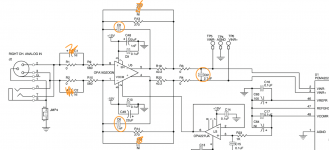
C61 is also part of the second-order low-pass filter and it probably provides the charge when the ADC connects its input sampling capacitor to its input to take a sample.
In fact when you analyse the output impedance of the circuitry to the left of C61, you will find it is equivalent to an inductance of 2 R19 R13 C5 in parallel with a resistance 2 R19 R13/(R19 + R13). Together with C61, it behaves similar to a second-order LRC low-pass.
In fact when you analyse the output impedance of the circuitry to the left of C61, you will find it is equivalent to an inductance of 2 R19 R13 C5 in parallel with a resistance 2 R19 R13/(R19 + R13). Together with C61, it behaves similar to a second-order LRC low-pass.
Last edited:
Aha!
I would like to set it's to something like -0,3dB at 20k. I will measure it and just make the caps correspondingly larget values for what I want - thats should work, right?
Like if I measure -0,3 at 60k I should make all 3 caps have 3 times bigger capacitance to move it to 20k?
//
I would like to set it's to something like -0,3dB at 20k. I will measure it and just make the caps correspondingly larget values for what I want - thats should work, right?
Like if I measure -0,3 at 60k I should make all 3 caps have 3 times bigger capacitance to move it to 20k?
//
If I did the math correctly, C5 = C6 = 18 nF and C61 = 39 nF (both NP0/C0G or some other good quality cap, definitely no X7R, X5R or other ceramic class 2 stuff) should result in about your desired roll-off, see the attachment. The normal cut-off frequency is around 657 kHz and the -0.3 dB point well over 300 kHz. I don't know whether the increased inductance will have any side effects on the performance of the PCM4222, you will just have to try and see.
Attachments
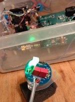
So Mic #2 give me trouble...
Measuring on the OPA I do have +15V at pin 8 and -15V at pin 4. But.... I also have +15 (or 14,88...) at oin 1 and pin 5... Did I fry an OPA?
Is the only way to really know to desolder the OPA and check 1 & 5 again?
//
Measuring on the OPA I do have +15V at pin 8 and -15V at pin 4. But.... I also have +15 (or 14,88...) at oin 1 and pin 5... Did I fry an OPA?
Is the only way to really know to desolder the OPA and check 1 & 5 again?
//
Last edited:
With the mic disconnected - it was not yesterday...:
Pin x rel to ground:
Pin x rel to ground:
- 0,26
- 0,5-0,7 flickering
- 0
- -15
- 1,52
- 1,51
- 1,52
- 15
If I randomly touch things on the side with the stabs, it comes and goes on pin 1... P2 seems to be steady.
//
//
Pins 1 and 2 are supposed to be connected, why do you see different signals there?
I suspect the low-frequency oscillations are related to the bootstrapping circuit working without the microphone capsule.
I suspect the low-frequency oscillations are related to the bootstrapping circuit working without the microphone capsule.
OK so capsule conected - but Mic not connected to EVM input....
Pin:
Pin:
- 14,95
- flickering - on scope it has that waveform shown earlier above...
- 3 slowly decreasing
- -15
- 1,52
- 1,52
- 1,53
- 14,97
Is either pin 1 or pin 2 not soldered properly or is it a faulty board? There should be a direct connection between them.
- Home
- Source & Line
- Digital Line Level
- Fixed gain field recorder?