It looks like you now have a short from pin 5 to supply, or some other issue that causes a much too high voltage at pin 5. Pin 6 and 7 then follow 5.
Hmm, its really strange - never touched these pins.... Lets see how it looks after some charging...
//
//
And now I need some fresh fuses. Which I cant find in the aftermath of the move so off to the electronic shop tomorrow. Good I put them into the battery box. The problem is the metallic mic bowls... Need to do something there before I continue.
//
//
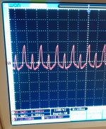
Hmm. After the event with the blown fuse that I suppose made the EVM board miss out of one of the + or - 15V, I now see efter the EVM op-amps (test points) what is depicted below. I was not there before and its on both channels. I just noticed as I was looking for output from mic #2 while tapping the table.
So close and now I sit with a possible injured EVM board. Mic #2 status looked to be better but now I need to first understand if I have a working EVM or not...
Sigh... But its my fault making a short in a mic while half assembled - I was to eager 🙂 and not taking precautions :-/
//
So close and now I sit with a possible injured EVM board. Mic #2 status looked to be better but now I need to first understand if I have a working EVM or not...
Sigh... But its my fault making a short in a mic while half assembled - I was to eager 🙂 and not taking precautions :-/
//
Attachments
Damn... There should have been a couple of reverse-biased rectifier diodes, preferably Schottky's, from the +/- 15 V supplies to ground, so the positive supply can't go negative and the negative supply can't go positive when a fuse blows.
Yes - or me using a pair of caps from each mic during development.
Marcel, seeing that oscillation, what would you say is its cause given the previous events?
Are the OP amps on the EVM boorked - or could even the ADC have been broken?
//
Marcel, seeing that oscillation, what would you say is its cause given the previous events?
Are the OP amps on the EVM boorked - or could even the ADC have been broken?
//
Unfortunately I really don't know. The amplifier ICs on the evaluation board have no direct connections to ground, which makes it far less likely that they go into destructive latch-up when the negative supply goes somewhat positive or the other way around. The outputs of the OPA1632's may have gone outside the specified absolute maximum rating for the input voltage range of the ADC chip, but the same can happen during normal use when you apply a too large signal. The current that the OPA1632's can deliver is typically 85 mA, while integrated circuits are usually designed to survive 100 mA under worst-case conditions for a short time during latch-up testing.
I don't think it's a parasitic oscillation, rather the sampling of the sigma-delta ADC. The frequency is about right and I would expect a spiky waveform because it is a switched-capacitor circuit (according to page 30 of the PCM4222 datasheet). Are you sure it wasn't there before?
What DC voltages do you see on the test points? They should be about 1.95 V. Is the spiky signal stronger or weaker when you measure at the OPA1632's side of R19 and R20?
When you measure them in circuit with the power off, do you get about 40.2 ohm for R19, R20, R21 and R22?
Thanks a bunch Marcel - I will check this later today. I'm quite sure they where not there. I have hooked up my scope probe several times to the 3 test pins after the OPAs on the EVM and this wasn't there before.
//
//
Marcel!
DC on test points:
CH1: 1,74
CH2: 1,86
Both same on +/-
On R20, its 4 times stronger on one side (cant figure out which really) 25vs100mV p-p. Same for R19.
All 4 resistirs show 40 ohm, EVM power off.
Merry C to all ;-D
//
DC on test points:
CH1: 1,74
CH2: 1,86
Both same on +/-
On R20, its 4 times stronger on one side (cant figure out which really) 25vs100mV p-p. Same for R19.
All 4 resistirs show 40 ohm, EVM power off.
Merry C to all ;-D
//
With power on, do you get equal DC voltages to ground on both sides of the 40.2 ohm resistors or are the sides connected to the OPA1632s closer to the intended 1.95 V than the sides that are connected to the test points?
The above figures was without the mics - just to be clear about that... just the EVM bu itself. I boxed things up quickly as in my new current living space, a project like this invades more or less the whole apartment and I thought I get some Christmas order into the joint ;-)
I'll check this soon - thanks for your help! I'm confident to make this sing eventually.
//
I'll check this soon - thanks for your help! I'm confident to make this sing eventually.
//
"Soon" has now passed :-D
Had I answered "single" for Marcels question in
https://www.diyaudio.com/community/threads/fixed-gain-field-recorder.373352/page-7#post-6695539
perhaps the power feed accident havant had the same impact?
Time to open the box and do some repairs.... 🙂
I shall add the protection diods that was mentiened in #525..
//
"a couple of reverse-biased rectifier diodes, preferably Schottky's, from the +/- 15 V supplies to ground"
https://www.electrokit.com/produkt/sb540-e3-54-do-201ad-40v-5a/
OK?
//
https://www.electrokit.com/produkt/sb540-e3-54-do-201ad-40v-5a/
OK?
//
Don't have your schematic handy, but would say that using Schottky diodes for protection tends to involve trading off three factors: Forward voltage verses current, reverse leakage current, and junction capacitance. One can calculate how hard they will clamp when forward biased under a fault current, how much of a problem reverse leakage might be, and the effects of hanging a capacitor equivalent to the junction capacitance where the diode would go.
Yes, those should do the trick if the issue was the positive supply going negative or the negative supply going positive."a couple of reverse-biased rectifier diodes, preferably Schottky's, from the +/- 15 V supplies to ground"
https://www.electrokit.com/produkt/sb540-e3-54-do-201ad-40v-5a/
OK?
//
I think the protection Mark had in mind in post #534 is putting Schottky clamping diodes from the ADC inputs to its supplies to ensure that the OPA1632 can't cause the ADC chip to go into latch-up when the signal is very large. For such a protection circuit, you would need four Schottky diodes per channel that can handle a maximum current well above 85 mA, but they should not be so large that their non-linear capacitance causes substantial extra distortion. You could also clamp the OPA1632 outputs, then they shouldn't be so large that their capacitance makes the OPA1632 unstable.
It would make sense to also add such a protection circuit (besides the big Schottky's from +15 V and -15 V to ground), if it is at all possible given the PCB design. I wonder why TI didn't put it on the evaluation board, though.
It would make sense to also add such a protection circuit (besides the big Schottky's from +15 V and -15 V to ground), if it is at all possible given the PCB design. I wonder why TI didn't put it on the evaluation board, though.
Last edited:

OK, digging in with the fault tracing...
Schema....

So there is a short between 5 and 6 using my ohm meter. What can cause this?
Is a short inside the OPA "possible"?
I have inspected and scraped with a knife... went back and verified an unstuffed board - ok.

Perhaps desoldering the OPA is the next best step to get a better insight into whats going on...?
//
Schema....
So there is a short between 5 and 6 using my ohm meter. What can cause this?
Is a short inside the OPA "possible"?
I have inspected and scraped with a knife... went back and verified an unstuffed board - ok.
Perhaps desoldering the OPA is the next best step to get a better insight into whats going on...?
//
- Home
- Source & Line
- Digital Line Level
- Fixed gain field recorder?