I did have a short of sort... it was the probe clip that touched 2 pins as i hooked it in... now I soldered to leads out from the pin header to hook probes to. OK - same level on both mod5 and 6.
No sound. To me, looks the same as before. 5 and 6 looks similar/identical...
//
No sound. To me, looks the same as before. 5 and 6 looks similar/identical...
//
Attachments
Ah OK - no clipping LED lit now with new bin file - sorry!!! forgot about that improvement of the situation 🙂
//
//
Last edited:
It suggests that a large part of the digital design works. There are three filters and an I2S interface in the digital signal path inside the FPGA, and the clipping detectors check the outputs of the second and third filters, so apparently everything is functional at least up to the second filter output. So at least it narrows down the problem.
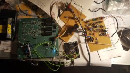
Status report from my side: I've modified a perfboard with a sigma-delta modulator that I had in the attic such that it provides a master clock at twice the bitrate. I hope I'll find the time to hook it up to the FPGA module and see what happens tomorrow, otherwise it has to wait until after my 1-week vacation.
Vacations are a good thing .. Honor it! 😀 You two have worked too hard on this ..
(Following with keen interest.)
Cheers
(Following with keen interest.)
Cheers
No problems what so ever Marcel. I'm in the middle of packing up my home for a move so I have plenty entertainment ;-)
I will also build the second Mic.
Vacation it is and I wish you a happy one!
Until later!
//
I will also build the second Mic.
Vacation it is and I wish you a happy one!
Until later!
//
I'm doing the experiment with the sigma-delta modulator and it works, provided the clock is up and running before the FPGA module is powered up. It does not recover from clock interruptions.
I first checked whether pins 66, 57 and 58 of the FPGA make contact with pins 10, 8 and 7 of SV1, as they are supposed to, and whether there were any shorts to neighbouring FPGA pins. On my module, it was all fine.
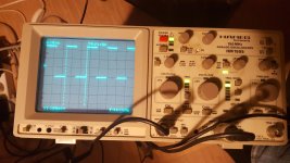
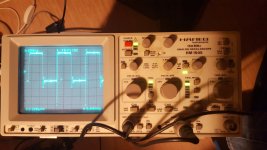
I then hooked up my sigma-delta perfboard to the clock inputs and to data inputs mod4...mod1, with mod5 and mod6 tied low (as it's a single- rather than a six-bit sigma-delta modulator). I checked if the FPGA module produced an I2S wordclock, bitclock and data signal. Scope plots are attached. All frequencies are a factor of two too low because my makeshift sigma-delta modulator runs at half the speed of the PCM4222.
I then hooked up a DAC and checked if I could get audio through. This also works fine. Disconnecting the FPGA module's supply stops the audio, it continues when the red LED turns on after reconnecting the FPGA module's supply. When the supply of the sigma-delta modulator perfboard that provides the clock is disconnected and connected again, there is no sound until I disconnect and reconnect the FPGA module's supply. That is, the FPGA does not recover from a clock interruption.
The speed is half of what it should be and with my set-up, I inherently get the same audio left and right, but to the extent that I can test it, it works.
I first checked whether pins 66, 57 and 58 of the FPGA make contact with pins 10, 8 and 7 of SV1, as they are supposed to, and whether there were any shorts to neighbouring FPGA pins. On my module, it was all fine.
I then hooked up my sigma-delta perfboard to the clock inputs and to data inputs mod4...mod1, with mod5 and mod6 tied low (as it's a single- rather than a six-bit sigma-delta modulator). I checked if the FPGA module produced an I2S wordclock, bitclock and data signal. Scope plots are attached. All frequencies are a factor of two too low because my makeshift sigma-delta modulator runs at half the speed of the PCM4222.
I then hooked up a DAC and checked if I could get audio through. This also works fine. Disconnecting the FPGA module's supply stops the audio, it continues when the red LED turns on after reconnecting the FPGA module's supply. When the supply of the sigma-delta modulator perfboard that provides the clock is disconnected and connected again, there is no sound until I disconnect and reconnect the FPGA module's supply. That is, the FPGA does not recover from a clock interruption.
The speed is half of what it should be and with my set-up, I inherently get the same audio left and right, but to the extent that I can test it, it works.
Attachments

Cool! So what you are saying is that most probable I do have a OK Mojo and I should most certainly see to that the EVM is started properly before powering up the Mojo. I'll check that on Saturday when I'm back to the kitchen based laboratory 🙂
//
//
Maybe it's good if you do the same continuity check on your module, just to be sure. You definitely have to power up the EVM first and then the Mojo.
That reminds me that I wanted to use I got my mojo working as the test signal for the test with the DAC, but forgot all about that. Well, never mind.
That reminds me that I wanted to use I got my mojo working as the test signal for the test with the DAC, but forgot all about that. Well, never mind.
🙂 I see you use coax to connect to the demodulator - I have a few meter of that cable - should I use it here? How do you do the ends - solder the core and just stick them in?
//
//
I connected the FPGA inputs via very thin 75 ohm coax cables. I stripped the last centimetre or so and connected it to a header that I plugged into the FPGA module's header. The advantage is that the line impedance is predictable, so I know what series termination resistor to use to get rid of reflections. The disadvantage is that even these very thin coax cables are not very flexible.
In fact that's why I used normal flexible wires for the connection to the DAC, despite the uncontrolled characteristic impedance.
I don't know.
The clipping LED works, so apparently the clocks from the EVM and the modulator signals (or at least the most significant ones) reach the FPGA. On the output side, you have a word clock that looks fine, a bit clock that looks like a serial data signal and no data. If that were due to a wiring problem (or connector problem or FPGA module soldering problem), the data signal would have to be connected to the bit clock wire and the data wire left open.
If it were due to transmission line reflections between EVM and FPGA, I would expect the digital clock module inside the FPGA not to lock. It shouldn't do anything at all then, except turning on the red LED.
If it were on the edge between working and not working due to reflections or crosstalk between the digital signals, then the extra ground wires should have helped to some extent.
Last edited:
For flexible coax, maybe try some RG-174 -- Belden 8216 or some such. A 100ft spool usually lasts me quite a while.
It's a little heavier load at 50 ohms. And the trade-off for small size and flexibility is that it's a bit lossier -- but usually not enough to matter in the short sections useful for test connections.
If a 100 ohms series termination load on your 74HCxxx outputs bothers you too much, cobble up an ~10,4:1 attenuator with 470 ohm series and 56 ohm shunt resistors.
Cheers
Last edited:
Belden indeed has some thin and flexible coax cables, also 75 ohm. I use about a metre of it at home for a cable TV signal that has to pass under a threshold, where there is a gap of only a few millimetres between the threshold and the floor.
I don't see how an attenuator could work, because with an attenuator, you won't have recognizable CMOS logic levels anymore.
I think the first thing I would try would be a continuity check from the FPGA package pins to the S/PDIF interface.
I don't see how an attenuator could work, because with an attenuator, you won't have recognizable CMOS logic levels anymore.
I think the first thing I would try would be a continuity check from the FPGA package pins to the S/PDIF interface.
I think the modulator output of the EVM is meant for 1.27 mm pitch flatcables. You get ground-signal-ground-signal-ground then, so good shielding and ground returns very nearby. The characteristic impedance of this flatcable 3319/10-100 3M Electronic Solutions Division | Mouser Nederland also matches the 100 ohm EVM's series termination resistors. (I don't mean to suggest that you buy 30.48 metres of this specific type, I haven't even checked if the number of conductors is what you need, it was just the first 1.27 mm pitch flatcable I found with a good datasheet.)
Last edited:
I cant see in the EVM manual that all pins behind the signal carrying ones are ground... but they should be I suppose. Can I poke around with my AVO freely on/between the pin-headers of the Mojo etc without a riks to damage anything? All power off of course..
//
//
- Home
- Source & Line
- Digital Line Level
- Fixed gain field recorder?