OK - a lose solder joint...
So:
Out from mic:
+ side: 2,01V
- side: 2,97V
Drain-Ground: 6V
OK?
//
So:
Out from mic:
+ side: 2,01V
- side: 2,97V
Drain-Ground: 6V
OK?
//
Much better, but I think it would be a good idea to short the silicon diode to get the voltages closer together.
Ideally yes, but to get the offset below 200 mV, you may also have to increase the resistor that sets the current through the LED, or use a different colour of LED, or add an extra resistor across the filtering capacitor of the diode stack to make an extra voltage divider.
Is any of those options feasible without damaging something? If not, I'd say just short the silicon diode and accept the offset you get.
Is any of those options feasible without damaging something? If not, I'd say just short the silicon diode and accept the offset you get.
It's doable for sure - I will try your different advice.
When I ordered components I did order a couple of trim potentiometers - I think I got 5kohm... usable somehow?
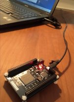
Same thing happened when I run the programming .exe file. The leds that where running as I hooked the board to a USB port for the first time stopped running and all LEDs went out. I suppose that means that the FPGA code was somehow changed. But the programming program has a progress-bar that never started to show anything happening.
What software did you use to make the program Marcel? And have you programmed yours?
//
When I ordered components I did order a couple of trim potentiometers - I think I got 5kohm... usable somehow?
Same thing happened when I run the programming .exe file. The leds that where running as I hooked the board to a USB port for the first time stopped running and all LEDs went out. I suppose that means that the FPGA code was somehow changed. But the programming program has a progress-bar that never started to show anything happening.
What software did you use to make the program Marcel? And have you programmed yours?
//
I have a dual-boot computer, used ISE14.6 under Windows to generate a .bit file, chopped off the header with a hex editor under Linux, changed the name to .bin and programmed it into the FPGA board with a program of which I've forgotten the name under Linux.
The program indicated that programming and verification had succeeded and the LEDs on the board switched off. I haven't checked if it does anything useful.
Edit: it was Mojo Loader, see
https://www.diyaudio.com/forums/dig...fixed-gain-field-recorder-30.html#post6737264
The program indicated that programming and verification had succeeded and the LEDs on the board switched off. I haven't checked if it does anything useful.
Edit: it was Mojo Loader, see
https://www.diyaudio.com/forums/dig...fixed-gain-field-recorder-30.html#post6737264
Last edited:
Regarding the voltage, you could:
1. Short the silicon diode, temporarily connect a 5 kohm potmeter in series with the 2.8 kohm that supplies the LED, turn it until the voltages are equal (this may not work, you may run out of range), measure the resistance of the series connection and replace potmeter and resistor with a fixed resistor with the same resistance.
2. Short the silicon diode, measure the voltage again, calculate (or let me calculate) what resistor to put in parallel with the filter capacitor of the diode stack and put it there.
What method would be most practical?
Okey - so turning black is not necessarily bad 🙂 Maybe we should have had som slow LED indication from the filter 🙂 running OK / indicating the mode...
When you loaded your board with the Mojo Loader, which I also use, did you indeed see the progress bar do something while loading it? How long was the duration of this programming procedure. What kind of indication did you get that it was finished?
Is there a way for me to understand if things went OK with loading except trying to start and see if it filters.
I'll start with 2. above - what is the gain by optimising this - relive the stress on the CMRR of the input of the EVM?
//
Last edited:
I think the progress indicator worked, but I'm not sure. The program certainly indicated that programming and verification had succeeded.
About the voltage: when the voltages are close, you have a slightly higher maximum sound pressure level and possibly slightly less distortion from the ADC, although ADC distortion is probably less than microphone distortion anyway. You don't use a substantial part of the ADC's differential input voltage range for offset anymore, so you can use it for audio instead.
About the voltage: when the voltages are close, you have a slightly higher maximum sound pressure level and possibly slightly less distortion from the ADC, although ADC distortion is probably less than microphone distortion anyway. You don't use a substantial part of the ADC's differential input voltage range for offset anymore, so you can use it for audio instead.
Last edited:
Thanks!
Took out my Win7 ol' laptop. Could event find CM & LTP settings panel... really strange... the Mojo Loader wants a COM port number but I cant find any COM ports.. on a windosw machine - world's crazy... 🙂
//
Took out my Win7 ol' laptop. Could event find CM & LTP settings panel... really strange... the Mojo Loader wants a COM port number but I cant find any COM ports.. on a windosw machine - world's crazy... 🙂
//


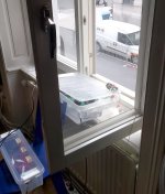
Below is a mono track of the street sound outside my window in central Stockholm. I gained it 30 dB. Even if mono, replayed on my system I'm quite happy with the "stage" and resolution.
Sound-file is in a .zip - please remove .mp4 extension...
//
Sound-file is in a .zip - please remove .mp4 extension...
//
Attachments
Last edited:
Is it possible to McGiver something like post #322 but from the FPGA board? The Ian board is a bit tricky to get in to the box... but its doable for sure!
//
//
- Home
- Source & Line
- Digital Line Level
- Fixed gain field recorder?