Looks like they use four different ADCs per channel with different gains, and then have some DSP algorithm select the most suitable one. The noise level is pretty good, by the way, with a noise figure < 4.2 dB(A) relative to 200 ohm.
OK - so I reversed the connection so that the Mic+ goes in to the + on the board.
Then I did proper measurements out from the Mic - forget all other above.
This makes sense even for me 😉
Mic / Diod / No-Diod
+ / 2,05 / 2,05
- / 2,98 / 2,35
//
Then I did proper measurements out from the Mic - forget all other above.
This makes sense even for me 😉
Mic / Diod / No-Diod
+ / 2,05 / 2,05
- / 2,98 / 2,35
//
So with the diode shorted, after a few minutes, it's + 2.05 V, - 2.5 V? If so, then a resistor of about 22 kohm...24 kohm across the filter capacitor of the diode stack should correct it. (Assuming a shorted silicon diode, so the "stack" only consists of an LED.)
Last edited:
You mean they switch ADC dynamically depending on level?
If so; Nasty - no like...
//
I guess so, but I don't know the details. It's patented, so you can look up what they do if you manage to find the patent somehow. I didn't see a patent number, unfortunately.
So with the diode shorted, after a few minutes, it's + 2.05 V, - 2.5 V? If so, then a resistor of about 22 kohm...24 kohm across the filter capacitor of the diode stack should correct it. (Assuming a shorted silicon diode, so the "stack" only consists of an LED.)
Great - soon to be tested.
//
No it is not my product but I've used it in many broacast and music installations for a long time, it is the sole ADC with this level of performances (158dB dynamic range). By the way, it is not really a preamp because conversion takes place at the input.Cool! You have caps in the signal path?
Are these your products?//
There is not any cap in signal path, it is a full floating input with a transformer in digital domain.
It complies to your request : no gain adjustement is needed at input because it accepts +24dBu and the input noise comes mostly from the mic internal noise.
This solution is expensive, part of bigger pro systems and not DIY but it shows that the idea of a preamp without gain adjustement is possible.
I think that first patent was US6028946A.It's patented, so you can look up what they do if you manage to find the patent somehow
Last edited:
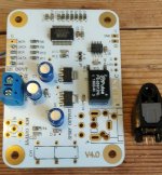
Hmm, room is limited... Ian IO board is big.
Marcel, I have an other board lying around... what say you - possible to use do you think?
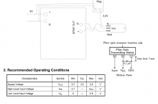
It says s/pdif out but can I connect an opto TX to that directly and if so, how?
//
Marcel, I have an other board lying around... what say you - possible to use do you think?
It says s/pdif out but can I connect an opto TX to that directly and if so, how?
//
Attachments
Last edited:
Is this a good start? Or a working one?
Or is the problem that that board will have a signal going 5V i.e. to high for the TOTX141?
//
Or is the problem that that board will have a signal going 5V i.e. to high for the TOTX141?
//
Attachments
Last edited:
So with the diode shorted, after a few minutes, it's + 2.05 V, - 2.5 V? If so, then a resistor of about 22 kohm...24 kohm across the filter capacitor of the diode stack should correct it. (Assuming a shorted silicon diode, so the "stack" only consists of an LED.)
Like this...
Now that I'm getting near I don't want to break anything... 🙂
//
Attachments

The
G
-
+
Is this for AES/EBU balanced i wonder?
Do I use only G and + I suppose?
//
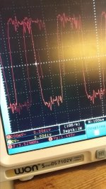
Could be, but maybe it's just transformer-coupled S/PDIF. Can you find more information about the board or measure with a scope what kind of signal levels you get?
The voltage swing and DC level of S/PDIF are not suitable to drive a CMOS input, that's why I suggested AC coupling and biasing around the trip point in post #322. Maybe it's better to use 10 times larger resistors and not terminate the output properly, then you get almost twice the swing.

- Home
- Source & Line
- Digital Line Level
- Fixed gain field recorder?