Makes sense! What about my jibber jabber in post #138? Sorry for the crude images… on mobile currently.
Obviously curious about that other OS trick pa was talking about…
Obviously curious about that other OS trick pa was talking about…
Get the right combination of R1 and R2 then the spectra are relatively insensitive to load resistance and most of the SIT variabilities.
I ran simulations across 6 SITs with significantly different parameters and both 4 Ohm and 8 Ohm loads. The spectra looked good in all combinations.
I ran simulations across 6 SITs with significantly different parameters and both 4 Ohm and 8 Ohm loads. The spectra looked good in all combinations.
Yes, but if you look at the arrangement in the zenductor, in between the bias resistor is interposed with a capacitor and ground… according to Nelson in his article, the bias resistor does not degenerate the mosfet…. I guess that is what I was trying to see if that is what Nelson was talking about.
You can do better..
It's fairly dumb. I tell you, a prize for a good answer. I will post it tmorrow...
It's fairly dumb. I tell you, a prize for a good answer. I will post it tmorrow...

What I see is that the speaker out from the SIT drain allows Class A single ended output.
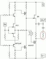
The speaker out from the mosfet drain can be controlled by the resistor between the mosfet drain and the capacitor connected to the speaker output. This resistor can be set so the amplifier is more single ended or more push-pull.
When set for more push-pull output, the amplifier output into lower speaker impedance (such as 4 Ohm) will allow for much higher power output than into speaker with higher speaker impedance (such as 8 Ohm).
When set for more single ended output, the amplifier output into lower speaker impedance (such as 4 Ohm) will be lower power output than into speaker with higher speaker impedance (such as 8 Ohm).
This is all set by one resistor which controls the amount of amplification that the mosfet provides.
Schematic with resistor noted:
Attachments
Last edited:
I think I have embarrassed myself enough for one night…. I follow what you are saying, if that is the case, then as a designer, one cannot assume what the customer will plug into the amps. So the question is, how does one design for both speakers in mind, 4 ohm speakers push pull, 8 ohm speakers single ended… maybe that is what pa was getting at. I know old school tube amps used to have different outputs connections for the types of ohm’s speakers connected. I doubt that is what is going on here.
Attachments
No speaker is exactly 4 Ohm or 8 Ohm over the whole frequency range, or even 4 Ohm or 8 Ohm at any frequency.
There are all sorts of assumptions and compromises in design, and the designer makes choices to suit his goals and preferences.
There are all sorts of assumptions and compromises in design, and the designer makes choices to suit his goals and preferences.
This time possibly no optocoupler, a TO-92 can be seen near the SIT and the 3Watt combo. Maybe done like in A3 or ZM like......Algar emi had hawks eyes.......
The simplified circuit appears to function nicely without R2 and C2. Perhaps the reason for those components is to allow R1 to be big enough for an optocoupler bias circuit but still have strong output from the PFET. No other magic involved.
:--))
This SIT5 looks great, 80 volts DC requirement is a bit much for me. I have now 40V on my 2SK182 and that should suffice. Could that be used too? 40V@1.5Amp = lots of watts already.Simulations show that the SIT-5 output stage is amazing. So far I have discovered several major improvements over any of the mu-follower follower MUFF stages
I use it for a 4 ohm speaker (pertained to be real flat, Ben: the Magnepan, but I'm sure this is not correct as there is a filter)... Will this SIT schema work well into that 'low' load too? I mean, the MU follower is related/designed/optimised to a standard load, isn't it?
I love the DC coupling (many of us have a SIT with a slight leaking gate, <400µA) - but how is the DC bias I need set? (I now have about -6.5 to -7.0Volt if memory serves me well)
If we take the extra green output capacitor as a supercapa = 1F: that has been used before as a Double Nelson output on a source resistor . . .
This way, the Rs becomes just a voltage shifter.
(Sorry Pa, this design unintentionally gets bigger and bigger)
Last edited:
Where did you see a TO-92 device? I didn't see it an any of the 6Moons pictures.This time possibly no optocoupler, a TO-92 can be seen near the SIT and the 3Watt combo. Maybe done like in A3 or ZM like......Algar emi had hawks eyes.
:--))
My SIT-3X amplifier has an undegenerated SIT/PFET (2SK182ES / IXTN40P50P) complementary follower output stage. I just made some measurements of the gate-to-gate voltage from a cold start (25C) to running temperature.
V(Gsit, Gpfet) started at -1.5V and stabilized at -2.05V after 30 minutes.
In the SIT-5, the quiescent voltage the SIT source to the PFET source will be I0*R1.
Thus the gate-to-gate voltage is likely to be close to zero.
Nelson's comment in post #44 https://www.diyaudio.com/community/threads/first-watt-sit5.418023/post-7879720
The interesting thing is the complementary circuit which biases the output SIT.
My guess: The Mosfet is connected through a resistor divider network to SIT and Output. Make this resistors ratio 1 : 5 and the Mosfet voltage contribution to the output should be five times less than that of the SIT. That is 20%…
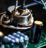
Comparing both 6moons pictures, we can see a blue wire on the mosfet side, near the two 1R resistors, then the same blue wire on the SIT side, between one resistor (maybe paralleled with a smaller cap), then 4 power resistors, and an other smaller cap., so maybe the output network is split as well between side, and between section with separate cap/resistors…
This blue wire may well be the output wire to the rear speaker connector.
To resume it seems there are smaller cap, maybe 470uf as we can see in parallel with each resistors at the output, in addition to the larger 5600u coupling caps…
The assumption of the SE mode in 8 ohms, and then push-pull in 4 ohms would also explain the unusual output power spec, clever…
As for the big caps 80V voltage rating, we can assume all large caps are the same in the amp, including the power supply pcb, Nelson uses parts with safety margin, 80V caps are just perfect for a 60V supply, with margin. And we know Nelson loves to re-use the same parts everywhere… I would go with a 60V supply. Finally he’s probably re-using the same power transformer, so we can assume the same secondary voltage as previous amps, but in series for a single voltage supply, in monoblock form, one per chassis/channel.
SB
Last edited:
What if Pa simply made it so the MOSFET contribution be relative to the current contribution to the load? That way, at lower levels or perhaps even moderate ones the character is almost entirely single ended. And at higher current draws the MOSFET contribution increases and gives the extra power needed whilst the SIT contribution and possibly tailored source resistance on the MOSFET ensures dominant 2nd harmonic all the way. So, sort of a hidden, but beautiful, beast within.
I have owned J2s and SIT 1s and can assure you that Mr. Pass does not use capacitors with generous voltage margins for decoupling.
I have a higher than usual line voltage and the J2 supply caps all developed bubbles at the top. Nothing ever went wrong. But they were within a volt or two of the rating.
I think the caps were used on purpose - not a mistake. Same with the SIT 1s. There are many who think that is the best way to use an electrolytic capacitor.
I would bet if those caps are rated for 80 volts the voltage supplied to them is close to that.
The bubbles are just the top plastic being deformed by the shrinkage of the plastic sleeve around the cap, this due to the heat inside the amp. Underneath you will probably find the aluminum case is ok.

As I said there was never a problem - but there is no question the voltage on the caps was close to their rating.
I am no longer using those amplifiers so I have no idea if any problem ever ensued.
My point was not to complain about the caps deformation; just to say there was not a "generous" gap between rating and the voltage across the caps.
The bubble is what drew this to my attention. I had no idea what caused it - but I have never had caps do this with other amplifiers.
- Home
- Amplifiers
- Pass Labs
- First Watt SIT5