Hi
I have the same models as you Oreo, but my
.model 10N20-75 has; "m=0.7 VJ=2.5 IS=4.0E-6 N=2.4 mfg=IH151206" at the end the same as the .model 10P20-75.
Does anyone know if this makes a difference or not.
Those numbers are what my 10P20-75 has,my 10N20-75 doesn't have any of those or the IH151206.My 10n20-25 has those numbers.Not sure one way or the other,hopefully the fellows that came up with these models will chime in.
Those parameters are for the body diode, maybe not critical for the F7.
The MFG= parameter is just for the transistor list and doesn't affect the model, Ian used it to differentiate one batch of models from another.
The capacitance parameters being same between P and N models is probably a mistake, so I suppose it's possible there are different set of parameters for the body diode that also didn't make it into the models. I will ask Ian. In the meantime, this is the pair of models I have in my library with non duplicate capacitances:
.model 10N20-75C VDMOS (Rg=60 Vto={0.17-1.6m*50} Lambda=3m Rs={0.245*(1+2.6m*50)} Tnom={temp} Kp={1.30/(1+8.3m*50)} Ksubthres={0.095*(1+2.9m*50)} Mtriode=0.3 Rd={0.6*(1+3m*50)} Cgdmax=100p Cgdmin=5p a=0.25 Cgs=600p Cjo=1100p m=0.7 VJ=2.5 IS=4.0E-6 N=2.4 mfg=IH151206 Vds=200)
.model 10P20-75C VDMOS (pchan Rg=60 Vto={-0.535+1.7m*50} Rs={0.37*(1+3.4m*50)} Tnom={temp} Kp={0.995/(1+6.7m*50)} Rd=0.2 Ksubthres={0.12*(1+3.1m*50)} Mtriode=0.4 Lambda=5m Cgdmax=215p Cgdmin=10p a=0.25 Cgs=900p Cjo=1200p m=0.7 VJ=2.5 IS=4.0E-6 N=2.4 mfg=IH151206 Vds=-200)
EDIT: I will point out that the first post in the Better Models thread still links to the 2015 models for these transistors. This is not because I have been lazy, but because to my knowledge the models haven't been significantly re-fitted after that point. There has been a lot of experimentation with exactly what format we want to models to be in, how to handle the curly braces, and then LTspice XVII added tempcos to the model so most of the curly braces are now unnecessary. But then a lot of people refuse to use XVII because of it's futile "GUI improvements", so the original models still stand. And so on and so forth so now we have a bunch of different model versions floating around, some of them having picked up errors along the way. So I suggest to use the models linked in the first post, unless there is a specific reason to use the redundant models littered throughout the thread.
Last edited:
Thanks for digging into this, keantoken.
I smiled at your comment about GUI "improvements" - about 2 years ago I switched from Windows to macOS and imagine my surprise at loading XVII and wondering where to begin. 🙂
I smiled at your comment about GUI "improvements" - about 2 years ago I switched from Windows to macOS and imagine my surprise at loading XVII and wondering where to begin. 🙂
A quick question.
Got most of the parts in surplus to build my version of the F7. Including a chassis with heat sinks from an old project I’d like to recycle.
It’s the same as this stock photo. Heat sinks are 50mm x 90mm x 300mm each side.
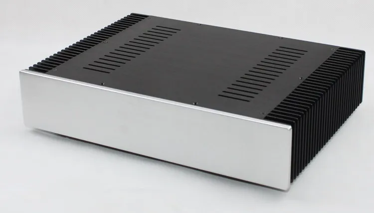
Opinions wanted if this will have enough heat sink for a wannabe F7 running at the stock +/-24VDC rails and outputs biased at 1A?
Got most of the parts in surplus to build my version of the F7. Including a chassis with heat sinks from an old project I’d like to recycle.
It’s the same as this stock photo. Heat sinks are 50mm x 90mm x 300mm each side.
Opinions wanted if this will have enough heat sink for a wannabe F7 running at the stock +/-24VDC rails and outputs biased at 1A?
A quick question.
Got most of the parts in surplus to build my version of the F7. Including a chassis with heat sinks from an old project I’d like to recycle.
It’s the same as this stock photo. Heat sinks are 50mm x 90mm x 300mm each side.
Opinions wanted if this will have enough heat sink for a wannabe F7 running at the stock +/-24VDC rails and outputs biased at 1A?
These look like 2RU tall heat sinks. I think you will need at least 3RU tall heat sinks for 1.0 A bias.
I am currently using 4RU tall heat sinks, which run 55 C + at 1.35 A (+/-22V rails) and about 50 C at 1.2 A. Actually, the lateral mosfets sound pretty good at a lower bias than standard mosfets. At 1.35 A, the amplifier starts to sound a bit harsh when fully up to temperature. So I've settled on 1.2 A (theoretically 26.4 watts of bias)
Yes - I looked at this and I think you need at a minimum the 3U heatsinks in the Dissaponte line in the DIY Store. I tried to make the dissipation numbers work on a 2U chassis, but they don't.
Also - some reviews of the F7 indicate it gets VERY hot in the factory configuration, which is closer to 3U.
Last edited:
Does it have the same or more ventilation on the bottom panel? On some of the "China" boxes, the bottom plate is solid, no holes.
And, you could put one if those small silent computer fans to circulate cool air too, if necessary - a temperature controlled one works quite well
And, you could put one if those small silent computer fans to circulate cool air too, if necessary - a temperature controlled one works quite well
Hi wtnh, oreo382,Those numbers are what my 10P20-75 has,my 10N20-75 doesn't have any of those or the IH151206.My 10n20-25 has those numbers.Not sure one way or the other,hopefully the fellows that came up with these models will chime in.
Updated models are here Better power MOSFET models in LTSpice Post 301
A bit embarrassing🙁 -- the DC parameters got about a year of work and the cap values got forgotten ... after all that.
My apology for missing this. Thanks for noticing the problem.
sufficient
though, maybe you'll need Babysitter arrangement, in Summer months
Thanks ZM. Gives me some confidence to go ahead reuse the old chassis.
These look like 2RU tall heat sinks. I think you will need at least 3RU tall heat sinks for 1.0 A bias.
I am currently using 4RU tall heat sinks, which run 55 C + at 1.35 A (+/-22V rails) and about 50 C at 1.2 A. Actually, the lateral mosfets sound pretty good at a lower bias than standard mosfets. At 1.35 A, the amplifier starts to sound a bit harsh when fully up to temperature. So I've settled on 1.2 A (theoretically 26.4 watts of bias)
Thanks for your hands on experience here. The chassis I originally bought from EBay (China). I’ll probably be trying what I already have first. ZM thinks it’s sufficient, so will be a good place to start. After it’s built, and there are heat issues (and if I like the F7), I can move to a larger box to make it a Keeper.
Patrick
.
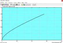
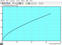
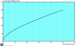
Thanks for the graphics Patrick. If the first graph (unlabeled) is for 300 x 50 x 90, it indeed looks better than the 3U 300 x 40 x 120 graph.
Last edited:
Does it have the same or more ventilation on the bottom panel? On some of the "China" boxes, the bottom plate is solid, no holes.
And, you could put one if those small silent computer fans to circulate cool air too, if necessary - a temperature controlled one works quite well
The bottom plate is slotted as the top, so your fan idea could help some too. Thanks!
Plus, it will be sitting on one of those IKEA open slatted bathroom tables. So lots of open free flowing air around the amp too.
Last edited:
Hi wtnh, oreo382,
Updated models are here Better power MOSFET models in LTSpice Post 301
A bit embarrassing🙁 -- the DC parameters got about a year of work and the cap values got forgotten ... after all that.
My apology for missing this. Thanks for noticing the problem.
Super! Thanks Ian.
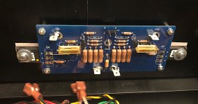
Some brave guy who built the UDNeSS wants to compare it to the F7.
So we modified the F5X PCB design for him for an alpha build.
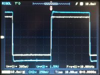
Works first time. Very easy to adjust. Very stable thermally, as expected.
Note that :
1. Only thin-film metal-film resistors were used (Dale RN55, RN70, CPF2). No metal oxide.
2. All trim pot are to be replaced by fixed resistors once set up in final case.
PCB size 128x55mm. MOSFET mounting distance 160mm.
No need for long & thin.
😉
Patrick
.
So we modified the F5X PCB design for him for an alpha build.
Works first time. Very easy to adjust. Very stable thermally, as expected.
Note that :
1. Only thin-film metal-film resistors were used (Dale RN55, RN70, CPF2). No metal oxide.
2. All trim pot are to be replaced by fixed resistors once set up in final case.
PCB size 128x55mm. MOSFET mounting distance 160mm.
No need for long & thin.
😉
Patrick
.
Attachments
Looks good Patrick. I'm actually considering trying this out with a pair of old 2SK135/2SJ50.
Mogens
Mogens
I was curious what double-die Exicon's would do.
Of course it only makes sense if you boot up the bias.
So with ECWs biased at 2A, I used Ian's models to do some simulations.
Of course you need to change some resistor values, but the maths is the same.
As you would expect, distortions drops almost by 2x for 8R.
And it is happier with 4R load.
Not that it is any surprise.
Patrick
- Home
- Amplifiers
- Pass Labs
- First Watt F7 review