For reference... Did Morde's jfets have a difference close to 2ma Idss between the J74 and K170?
I like accumulating data.
I'm interested in the the distortion spread at 0V offset (WRT P3 wiper) and either side.
My Focusrite Scarlett 2i2 died
I'm interested in the the distortion spread at 0V offset (WRT P3 wiper) and either side.
My Focusrite Scarlett 2i2 died
For reference... Did Morde's jfets have a difference close to 2ma Idss between the J74 and K170?
Idss values were 9,4/9,4mA for 2SK170 and 9,1/9,1mA for 2SJ74 with 22V feed. These were purchased from Punkydawgs.
For the Exicon lateral FETs See attached Vgs measurements at 1,2...1,4A and 22V rail voltage. This was done similarly to UDNeSS mosfet measurement in room temp with large fan cooled sink.
Attachments
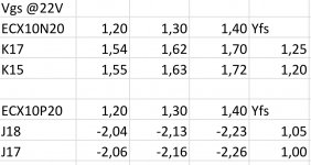
The particular combination of Vgs and Yfs of the laterals has a direct impact of H2 / H3 distribution.
This you can compensate partly with the trimmer.
Also lower Idss leads to higher gain in the first stage, and hence reduced distortion overall.
Patrick
This you can compensate partly with the trimmer.
Also lower Idss leads to higher gain in the first stage, and hence reduced distortion overall.
Patrick
I am using a 20 Ohm pot and seeing lower distortion @ 1 W. Also trying to figure out the matching issues with the laterals. One channel is 2H -100 degrees, the other is 2H +90. This is at 1.2A bias. 😀
Still experimenting, but so far really nice measurements and sound.
Still experimenting, but so far really nice measurements and sound.
I report some of the findings from the F7 clone alpha test phase here...
All kinds of measurements and tweaks were performed on basis of what Patrick (EUVL) instructed me to do. The starting point was the F7 clone circuit fed with a regular FW type of CRC power supply with +-22Vdc rails and 1,3 A bias. See the first attachment, with H2=0,13% and H3=0,03% into 8 ohm. The H2 value was 2x higher than what was expected from the LTspice simulation but the ratio between H2/H3 was quite close.
Next we tried what happens if bias current is raised to 1,5A. Well, no effect on H2, only H3 dropped by tiny bit.
The third iteration round was to see what happens with higher rail voltages. So I fed the amp with my lab supply through the CRC supply with different rail voltages. The results can be seen in the second pic I attached. It was noted that with +-25Vdc rails the distortion lowered quite significantly for both H2 and H3, but with +-28Vdc H2 was further halved while H3 stayed the same. So if you have the sinks and your PSU is up for the task, higher rail voltages can be recommended.
The fourth and the last tweak was to implement a 10 ohm trimmer pot for adjusting the source resistance of the JFETs as described in post #1537 by avdesignguru. So I measured the trimmer beforehand for a few turns to both directions (clock wise and counter clock wise) and the soldered it in and did distortion measurement for each turn of the pot. Results can be seen in the third attachment. The results indicate that the pot had effect only for the second harmonic. This was a cool measurement to carry out as you could see the harmonics change while turning the pot. 🙂 The DC offsets were adjusted after each turn of the pot before measuring.
In the end the listening test was done with distortion adjusted to H2=0,065% / H3=0,030% with the trimmer and the amp fed with +-22Vdc rails from the CRC supply.
My subjective listening impressions:
At first the F7 clone did not make a huge impression but the more I listened the more I started to like it. Similarly to UDNeSS it is a very pleasant and easy to listen to. Where it shines the most are vocals and soundstage representation. If my memory serves me correctly, I would say vocals and the feel of presence is a little better than with the UDNeSS. Maybe this is due to the tubey-like distortion profile...
Also bass goes deep but my Denon AVR-X3000 is a bit better in controlling the bass with my 4 ohm speakers.
All in all a very good Class A amp once again especially when considering the simplicity of the circuit. 🙂
Thanks a lot to Patrick for letting me test this mathematically derived F7 clone version. And obviously huge respect for Mr. Pass for these mind puzzling amps. 😀
Interesting,I have simmed your amp with 25V rails,9ma jfets,1.3 amp bias,10 ohm trimmer centered, and got almost exactly your results. Mine are 0.082% THD,H2 phase at +86 degrees (almost perfect neg. phase 2nd harmonic).My h2 FFT is -61db,h3 is -90db (referred to H1@0db).Looks like with a simple amp and good models you can get very close with a sim.
Interesting,I have simmed your amp with 25V rails,9ma jfets,1.3 amp bias,10 ohm trimmer centered, and got almost exactly your results. Mine are 0.082% THD,H2 phase at +86 degrees (almost perfect neg. phase 2nd harmonic).My h2 FFT is -61db,h3 is -90db (referred to H1@0db).Looks like with a simple amp and good models you can get very close with a sim.
Which models did you use? Did you use the models posted by IanHegglun?
Interesting,I have simmed your amp with 25V rails,9ma jfets,1.3 amp bias,10 ohm trimmer centered, and got almost exactly your results. Mine are 0.082% THD,H2 phase at +86 degrees (almost perfect neg. phase 2nd harmonic).My h2 FFT is -61db,h3 is -90db (referred to H1@0db).Looks like with a simple amp and good models you can get very close with a sim.
Very cool to hear that my measurements can be reproduced! Gives me a lot of confidence about my measurement setup. Thanks for sharing the info. 🙂
Just did a sim of your 6 CCW in your table and got 0.048% THD,exactly the same as you so there is repeatibility.I also did your 2 CW
and got 0.091% THD,very close to your results for distortion.Only thing is my sims show a 30db difference between H2 and H3 wheras yours show a 10db difference.I have no idea why that is seeing as the H2 and H2 % THD's are almost identical.Maybe seeing as the H3 is so small that 20db is not a large actual percentage.
and got 0.091% THD,very close to your results for distortion.Only thing is my sims show a 30db difference between H2 and H3 wheras yours show a 10db difference.I have no idea why that is seeing as the H2 and H2 % THD's are almost identical.Maybe seeing as the H3 is so small that 20db is not a large actual percentage.
Last edited:
Which models did you use? Did you use the models posted by IanHegglun?
I used Ian's latest models,the 75 degree celsius ones as I think they reflect the actual mosfet junction temps. I have custom made jfet models I cobble together from toshibas graphs by scaling the difference between the published curves and the curves I need.I think they are pretty accurate as I can run an Ltspice stepped Id vs vgs plot and the results come out pretty close to Toshibas graph results.
Thanks, I found the models. It was just a few pages back. Somehow I missed that conversation.
I finally have finished reading all 166 pages of this thread and am now gathering parts to build it. I have several options for chassis and heatsinks and am just wondering what the general consensus is on optimum rail voltage and bias current? I think I understand the various F7 iterations seem to like about 1A bias using the J162/K1058, but I am going to be using J49/K134. Anyone built one with the old Hiatchi FETs like mine?
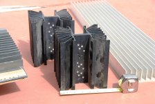
If it really is only biased at 1A then I can use much smaller heatsinks than I originally planned and can save the big sinks for another project like SissySit, Turbo F5 etc. I have 2 very nice Star Wars type heatsinks, already drilled for TO-3s and would like to use them. They are 6.25"x6.25" and 7" tall, gives a rise of .254*C/W which would give a 20* rise above ambient with 80W dissipation per channel, and based on the F7 manual, it dissipates 160W for 2 channel. Given that 160W spec, and standard 24VDC rails, would lead me to think the bias in the real F7 is a bit higher than 1A, anyone concur or confirm?
Look forward to hearing from you as to what the best bias and rail voltages would be for the F7.
Cheers
Attachments
Last edited:
Those sinks look adequate.Typical FW power supply is about 23 Volts D.C. 1 amp gets you roughly 20 Watts.Mine runs at that.
((46*1.1)*2)/0/65 = 155 watts, or within margin of error.
Linear power supplies are usually 65% efficient.
Linear power supplies are usually 65% efficient.
Linear power supplies meaning a bench type supply.A transformer,diode,capacitor system like the Firstwatt has to be at least 90-95% efficient.
I finally have finished reading all 166 pages of this thread and am now gathering parts to build it. I have several options for chassis and heatsinks and am just wondering what the general consensus is on optimum rail voltage and bias current? I think I understand the various F7 iterations seem to like about 1A bias using the J162/K1058, but I am going to be using J49/K134. Anyone built one with the old Hiatchi FETs like mine?
If it really is only biased at 1A then I can use much smaller heatsinks than I originally planned and can save the big sinks for another project like SissySit, Turbo F5 etc. I have 2 very nice Star Wars type heatsinks, already drilled for TO-3s and would like to use them. They are 6.25"x6.25" and 7" tall, gives a rise of .254*C/W which would give a 20* rise above ambient with 80W dissipation per channel, and based on the F7 manual, it dissipates 160W for 2 channel. Given that 160W spec, and standard 24VDC rails, would lead me to think the bias in the real F7 is a bit higher than 1A, anyone concur or confirm?
Look forward to hearing from you as to what the best bias and rail voltages would be for the F7.
Cheers
I cannot confirm where Papa biases the real F7 outputs, but I have done all my testing at 24 volts/1.2 amps and things seem fine using the heatsinks in the DIY Store Dissipante 3U chassis. NB - I am using Exicon laterals in TO247 packages with Keratherm insulators, so your mileage will vary with your devices. I would suggest doing some thermal measurements, maybe with power resistors bolted to your heatsinks, or just go for it and vary the bias while monitoring the heat rise.
Thanks Boyz,
Sounds like the black Wakefield sinks will be just fine, they are extrusion 1541 or 486 for the precut version. Mine are 7" so must have been custom cut from the full length. So at that bias and rail V it will only dissipate 60W/channel. I wonder if the devices will be hot enough to "sound correct"? I would imagine that the temp of the die might have an effect on the sound. I'll also look to see where it puts the devices in their tempco curve.
Yes, pretty easy to mockup a test platform to confirm temp and dissipation.
Thanks!
Cheers
As far as "sound correct" the setting of the pot connected to the jfet source pins has a huge effect.I've varied my bias 100ma one way and the other but the jfet pot setting makes the biggest differrence to my ears.
Linear power supplies meaning a bench type supply.A transformer,diode,capacitor system like the Firstwatt has to be at least 90-95% efficient.
In the context of a whole class a amp efficiency is around 25% from what i've read.
Thanks Papa!
Back in the days I've completed my ACA and F5 projects and was searching for a new one. F7 instantly caught my eye by its simplicity. In my day time job "less is more" my main principle. I must give a try to this project. Even there is no schematics, even I have absolutely no knowledge, just a passion.
So I've read all the 150 pages, save every potential schematic and photo of F7, read about PCF, and start to figure out. Of course, I installed LTSpice for the first time (oh it takes time to become friends with this software), find all the models, and got lots of fun during the simulations 😀
Here I want to thank Mr. Nelson by letting guys like me educate myself in such a joyful way. It was pure pleasure and It was a way more helpful than having a schematic on hands.
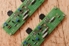
I've already started up my boards, tweaked up the bias, and played a bit with harmonic pot. Seems like everything is ok. In a couple of weeks I'll have time to come back, boot two boards and set it up. More to come.
Back in the days I've completed my ACA and F5 projects and was searching for a new one. F7 instantly caught my eye by its simplicity. In my day time job "less is more" my main principle. I must give a try to this project. Even there is no schematics, even I have absolutely no knowledge, just a passion.
So I've read all the 150 pages, save every potential schematic and photo of F7, read about PCF, and start to figure out. Of course, I installed LTSpice for the first time (oh it takes time to become friends with this software), find all the models, and got lots of fun during the simulations 😀
Here I want to thank Mr. Nelson by letting guys like me educate myself in such a joyful way. It was pure pleasure and It was a way more helpful than having a schematic on hands.
I've already started up my boards, tweaked up the bias, and played a bit with harmonic pot. Seems like everything is ok. In a couple of weeks I'll have time to come back, boot two boards and set it up. More to come.
Attachments
- Home
- Amplifiers
- Pass Labs
- First Watt F7 review