The resistors aren't 3.9k.That gives a bandwidth of over 1Mhz,the F7 is around 100khz bandwidth.Reread Patrick's post,he talks about an 11k resistor to ground.
What do you mean by "original".Nelson hasn't given us the original yet.Whatever is out there is peoples best guesses and i'd say some are very good ones.
There are clear pictures from Inside of an F7 on 6moons website. There you can see the number of resistors used and even some of the values as they are colour coded. For sure there is no 11k resistor to ground.
Maybe it's under the board.I've seen Nelson mention hiding components under boards.Maybe directly across the RCA jacks? At any rate the resistors are not 3.9k.I've built my own F7 and it has 39k.I have sims that show there is not 3.9k.
An externally hosted image should be here but it was not working when we last tested it.
copy from aliexpress, we can see the resistors
Last edited:
Would be nice when you stopp to give links to commercial clones of the F7......
This is not the intention of this forum.
This is not the intention of this forum.
thanks!
This is a picture for reference about the structure and value of the resistors, not a link
This is a picture for reference about the structure and value of the resistors, not a link
Please Dang..
May be the colour resistors are wrong, or the guy is just trying to sell his stuff.... there is a protection of Copyright on the design, values, and model... so stop sending pictures, build your own F7 and stop 'advertising' here! please.
May be the colour resistors are wrong, or the guy is just trying to sell his stuff.... there is a protection of Copyright on the design, values, and model... so stop sending pictures, build your own F7 and stop 'advertising' here! please.
spam...........OK. I've attached the basic idea. Draw this up in the modeling program of your choice (I used LTSpice) and start plugging in appropriate resistor values until you get something that works.
Last edited:
I'm starting to work on the F7 clone. Thank you very much, Mr. Pass! Thanks also to the diyaudio.com community.
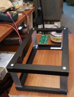
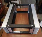
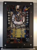
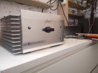
I started working on the First Watt F7 clone amplifier at the beginning of August this year. I made a supporting structure of aluminum elements measuring 31 cm x 22 cm x 12 cm.
I installed heat sinks on the sides of the frame.
Hacksaw, saw blade with fork, file and electric drill - my faithful helpers.
I installed heat sinks on the sides of the frame.
Hacksaw, saw blade with fork, file and electric drill - my faithful helpers.
Attachments


I made the F7 clone out of curiosity, wanted to check out all those good F7 reviews?
I was very impressed by the fact that after listening to the F7, many declared users of tube amplifiers started listening to music on the F7!
I will not elaborate on it, I will say briefly that I am also one of those people who, after listening to music on the F7 for the first time, cannot imagine listening to other amplifiers, even tube amplifiers!
Thank you for your attention and sorry for my English (google translator).
how did you set up the 3 pots to achieve the desired H2 negative spectrum?
any special distortion meter?
any special distortion meter?
I only measured the currents flowing through the power transistors and the dc offset at the speaker output with an 8R resistor. My ears fell in love with the sound of the F7 amplifier right away 🙂 The wonderful lightness of the brain decoding the acoustic signals generated by the speaker diaphragm driven by the F7 amplifier!
- Home
- Amplifiers
- Pass Labs
- First Watt F7 review