lower Rsen and higher Rfbp could increase the damping factor.
Would-it be possible to use the cable going to the negative terminal of the speaker as Rsen?
Connecting Rfbp with a cable directly to the - speaker terminal...
this could reduce some damping factor loss due to the cable resistance?
Would-it be possible to use the cable going to the negative terminal of the speaker as Rsen?
Connecting Rfbp with a cable directly to the - speaker terminal...
this could reduce some damping factor loss due to the cable resistance?
That would require either a highly resistive wire for the ground end speaker wire and extremely low value for Rsen. In either case I do not see any advantage over having a fixed and known value for Rsen of the PCB.lower Rsen and higher Rfbp could increase the damping factor.
Would-it be possible to use the cable going to the negative terminal of the speaker as Rsen?
Connecting Rfbp with a cable directly to the - speaker terminal...
this could reduce some damping factor loss due to the cable resistance?
F7 compatibility with 16 ohm speakers: would a resistor across the speaker terminals have any favorable effect for F7 driving 16 ohm 460Z Altec 15" in K-15 Karlson cabinets? Mr. Pass said the resistor approach was good for Sit-3 and current source amplifiers (and of no positive effect for ACAs). (ACA with 16 ohn Altec? post #5 10/16/2019.)
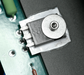
I ran bench tests matching pairs of ALF08N16 and pairs of ALF08P16 later FETs.
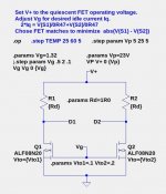
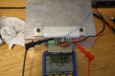
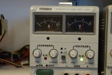
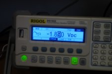
Show below are images of the lest circuit and images of the test rig where the FETs are clamped to a heatsink, power is from a bench supply, and gate voltage is from a waveform generator with adjustable DC output.
The first pair of ALF08N16 had only 25mA difference in drain current at Vds=23V and Id=600mA (for combined 1.2A current).
I tested only one pair of ALF08P16 FETs and obtained 80mA difference in drain current at Vds=-23V and Id=-600mA.
Conclusion: It appears easy to find pairs of these lateral FETs without current hogging problems.
Attachments
If you buy directly from Profusion, you can buy selected / matched ones.
And they are quite well matched.
Patrick
And they are quite well matched.
Patrick
I have two pairs of lateral Mosfets 2SK1058/2SJ162, but I don't know which ones belong together🤔.
How can I find the two complementary pairs back together? Looking for the simplest solution🙂
How can I find the two complementary pairs back together? Looking for the simplest solution🙂
Two MOSFETs with same Vgs at the same Id and same Vds make matched pair. So, measuring them is the only way to tell ...
Put MOSFETs on the heatsink, start with the lowest resistance of the pots and set the them so that A-meter shows 1A and read the Vgs, Write it down, mark the MOSFET and measure the next one. Don't mix up the polarity of MOSFETs,
Put MOSFETs on the heatsink, start with the lowest resistance of the pots and set the them so that A-meter shows 1A and read the Vgs, Write it down, mark the MOSFET and measure the next one. Don't mix up the polarity of MOSFETs,
Attachments
Last edited:
Thanks very much.
Maybe I should ask more specifically. I want to build my clone of F7 and have two 2SK1058 and two 2SJ162. How can I find the best P plus N channel pairs? Does it even matter?
Maybe I should ask more specifically. I want to build my clone of F7 and have two 2SK1058 and two 2SJ162. How can I find the best P plus N channel pairs? Does it even matter?
Exactly as explained in my previous post.... How can I find the best P plus N channel pairs? ...
As for cloning the current commercial product, try first to understand how it works.
IIRC, there is that place in Auburn.... How can I find the best P plus N channel pairs? ...


Looks the same to me, so I don't see why the rail voltage should be +32V instead of +24V for Exicon.ECX series from Exicon don't have the same dynamic range as 2SK1058 and 2SJ162. You have to use +32V rails or use the ECW series from Exicon they are better. I use ECW with 32V rails and they sound excellent.
Jfets don't have to be matched. Use J74 with Idss 3ma higher then K170
For gate resistors 47R is enough.
Attachments
My F7 emulation with ECX10N20 and ECX10P20 delievers comparable results.
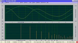
However some measurements are different from original specification, such as damping factor, which is about 20 only. I believe the cause lies in the power mosftes.
There are visible intermodulation products, so I was afraid to measure the IM factor.
The negative phase of H2 looks like in the picture book, but like I said in the beginning, this is just my emulation.
Attachments

What did you emulate, if I dare to ask the question?My F7 emulation with ECX10N20 and ECX10P20 delievers comparable results.
However some measurements are different from original specification, such as damping factor, which is about 20 only. I believe the cause lies in the power mosftes.
There are visible intermodulation products, so I was afraid to measure the IM factor.
The negative phase of H2 looks like in the picture book, but like I said in the beginning, this is just my emulation.
- Home
- Amplifiers
- Pass Labs
- First Watt F7 review