For stock I mean diyF5, Plain vanilla F5. I have already built few versions, that's why I have one too many that would be good to experiment with.
I'll try to calculate components and see how it goes.
D
One significant difference between the F5 and the F7 is the F5 has considerably higher open-loop gain (OLG). OLG=gm*Rload. This will affect the resistor choices. Look at the equations in post#442 http://www.diyaudio.com/forums/pass-labs/275921-first-watt-f7-review-45.html#post4585617 to understand how various resistor ratios depend on gm.
Vishay AC05 series for the big greenies.... 🙂
Thanks for response Generg
Interesting greenies 😀
Attachments
Thanks for response Generg
Interesting greenies 😀
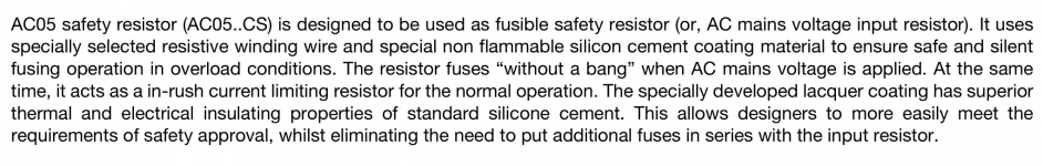
That statement belongs with the AC05xxx-CS series resistors that are only available in the 10R to 100R resistance range. http://www.vishay.com/docs/28894/ac05cs.pdf
That statement belongs with the AC05xxx-CS series resistors that are only available in the 10R to 100R resistance range. http://www.vishay.com/docs/28894/ac05cs.pdf
Next reference of resistors are Vishay AC05 simpler version without CS options ( fuse, in rush current protection )
http://www.vishay.com/docs/28730/acseries.pdf
Start with 0R1 resistance range.
Watt's new: The F7 amplifier is now in production with availability in March
Yeah good news !
FIRST WATT F7
Best regards 🙂
Last edited:
Or if you are lazy like me, and since the positive feedback loop of Type 2 is not supposed to screw up bias, you can deploy the P&P (plug and pray) method. Plug 10k for R1, 10k - 47k for Rfbp, 0R22 - 2R2 for Rsen, check for output offset and oscillation, do a listen and Pray that the Good Mysterious Power of Positive Feedback is not eluding your perception. 😀... I'll try to calculate components and see how it goes.
First watt F7 review
I always wanted to ask (I hope Nelson doesn't mind) what are those two black "boxes" on the L and N traces?

Sent from my iPhone using Tapatalk
I always wanted to ask (I hope Nelson doesn't mind) what are those two black "boxes" on the L and N traces?
Sent from my iPhone using Tapatalk
I always wanted to ask (I hope Nelson doesn't mind) what are those two black "boxes" on the L and N traces?
I think they're line filter capacitors.
Where did you get that picture? To me it look as some kind of ferrite-beads for EMI-purpose (You remember Mr. Pass` comment about improving HF immunity?).
Oh, I first misunderstood genergs comment.
F7 converts every singers voice to sound like Bon Scott.
F7 converts every singers voice to sound like Bon Scott.
These are AC DC soundconverters One of the secrets of First Watt.....
🙂)))
..cryogenicaly treated behind the sunset....makes conversion easier.
🙄
fun fuse
all nonsense....... 😀
the bitter truth
RST 4-BULK Bel Fuse Inc. | Circuit Protection | DigiKey
thanks guys for fun!
all nonsense....... 😀
the bitter truth
RST 4-BULK Bel Fuse Inc. | Circuit Protection | DigiKey
thanks guys for fun!
I have completed analysis of the 6 the combinations of Rload/Rsense resistor placement w.r.t. each other and ground. LTSpice simulations appear to verify the correctness of the equations shown.
Dear Ihquam,
I am quite impressed with your work and trying lo learn something, maybe building something on the way. I have many, probably dumb, questions.
I am trying to use the topology 2 to modify an F5 using positive feedback, as I was suggested.
Now the dumb questions:
1) What does "fbs" stand for ? (Rfbs)
2) Is gm the transductance of the mosfets ?
3) In your equation the Rfbn is calculated using the CLG (Close Loop Voltage Gain) but isn't the CLG a function of the Rfbn ?
I am trying to use LTSpice to see how things go. Please see if my assumption are correct:
a)The OLG can be measured removing all the feedback elements and measuring the ratio between a voltage in output and a voltage in input.
b)The CLG can be measured as ratio of the output over the input with the negative feedback applied.
Thanks in advance for any explanation.
Davide
- Ffbs stands for Resistance feedback shunt.
- gm is the (open-loop) transconductance of the entire amplifier chain. dIout/dVin.
- Yes, Rfbn affects CLG. The entire network of devices produces a set of simultaneous equations that can be solved in any number of different ways. The most useful formulation was to determine the resistor ratios as a function of CLG, and gm, leaving one free variable: Rsen.
a) OLG = gm*Rload. The equations were derived assuming that the amplifier behaves in the manner of the SPICE voltage controlled current source (G element). For the F7, the differential input voltage would be the voltage difference between the JFET gates and the degenerated source. This gets a bit tricky, since the source degeneration interacts with the P3 pot and the Rfbn/Rfbs feedback network. It requires experimentation with the simulation to get a proper estimate of gm.
b) CLG is the ratio output voltage to input voltage with ALL feedback applied.
b) CLG is the ratio output voltage to input voltage with ALL feedback applied.
Dear Ihquam,
I am quite impressed with your work and trying lo learn something, maybe building something on the way. I have many, probably dumb, questions.
I am trying to use the topology 2 to modify an F5 using positive feedback, as I was suggested.
Now the dumb questions:
1) What does "fbs" stand for ? (Rfbs)
2) Is gm the transductance of the mosfets ?
3) In your equation the Rfbn is calculated using the CLG (Close Loop Voltage Gain) but isn't the CLG a function of the Rfbn ?
I am trying to use LTSpice to see how things go. Please see if my assumption are correct:
a)The OLG can be measured removing all the feedback elements and measuring the ratio between a voltage in output and a voltage in input.
b)The CLG can be measured as ratio of the output over the input with the negative feedback applied.
Thanks in advance for any explanation.
Davide
Or if you are lazy like me, and since the positive feedback loop of Type 2 is not supposed to screw up bias, you can deploy the P&P (plug and pray) method. Plug 10k for R1, 10k - 47k for Rfbp, 0R22 - 2R2 for Rsen, check for output offset and oscillation, do a listen and Pray that the Good Mysterious Power of Positive Feedback is not eluding your perception. 😀
This was a good starting point to play with the simulation.
The main difference that I see, from my limited knowledge, between the F5 and the Type 2 is the point where the negative feedback is applied. In the F5 the negative feedback is applied directly on the gates of the jet, while in the type 2 is applied in the center node, that has to be floated with the Rnfbs.
D.
Is it ok to post up a circuit with some values, or should I keep this secret (I'm good at that, haha)?
Is it ok to post up a circuit with some values, or should I keep this secret (I'm good at that, haha)?
From post #422: http://www.diyaudio.com/forums/pass-labs/275921-first-watt-f7-review-43.html#post4581165
I'm dumb ...... and I know I'm dumb ..... and that's certainly why there is a fact that I know exact schm of F7 ........ but am I wrong in thinking that exploring this circuit in tiniest possible detail in public is somewhat before it's time ?
wasn't it possible to keep it private at least 6 months , a year ........ whether Papa decide to seize production of F7 , or not ?
we have enough written info , pictures , enclosed articles from Yore ....... it is not hard to guess it , at least for those equipped with more than (mine) two cells ...
this way , slabbing another iteration after iteration , it seems that all we are waiting for is just Papa's nod - "that's Real McCay!"
I'm pretty sure that everyone would get confirmation from Papa , in private correspondence .....
to be frank , all what world cloners/IP stealers need to do is simply to buy F7 , and draw schmtc from it ....... as the case is with 95% of amps on market
but , I don't think that our guessing/deciphering joy needs to be there to help them ..... even if I'm not sure in NP's intentions , as generg already put ...
at least babelfish it , making it 50% more complicated , say that you cracked it ...... then nobody on ebay will sell Fx knockouts , be it exact or almost exact thing ....
- Home
- Amplifiers
- Pass Labs
- First Watt F7 review