Thanks 2 picoDumbs. It is specific to this special amp.
No, see post #535 http://www.diyaudio.com/forums/pass-labs/275921-first-watt-f7-review-54.html#post4614010.
Thanks lhquam.
In my opinion it's the combination of both positive and negative feedback loops that gives you the desired properties otherwise I don't think Nelson would have used both negative and positive feedback in his F7 amp.
Thank you lhquam for the working schematic of post #544 of a balanced F7.
Two questions:-
Can this be implemented by doubling 2SK1058, 2SJ162 as Output devices; if yes, what would be the optimal value of Source Resistors?
Is the sound of your Implementation close to the actual F7 described by 6moons?
Thanks.
Two questions:-
Can this be implemented by doubling 2SK1058, 2SJ162 as Output devices; if yes, what would be the optimal value of Source Resistors?
Is the sound of your Implementation close to the actual F7 described by 6moons?
Thanks.
Thank you lhquam for the working schematic of post #544 of a balanced F7.
Two questions:-
Can this be implemented by doubling 2SK1058, 2SJ162 as Output devices; if yes, what would be the optimal value of Source Resistors?
Is the sound of your Implementation close to the actual F7 described by 6moons?
Thanks.
If Vgs of the 2SK1058, 2SJ162 output fets are reasonably well matched at the idle current then you should not need any source resistors.
I have only run simulations of the balanced amplifier, but I am fairly confident that it will perform well, perhaps requiring a few resistor tweaks. The harmonic spectrum shown in the simulations closely matches the F7. I have built an approximation of the FirstWatt F7 and the measurements agree fairly well with the simulations.
I don't use source resistors on my amps using lateral mosfets, but I do check that they match well.
So far my experience has been they nearly all match identically provided they come from the same manufacturing batch.
So far my experience has been they nearly all match identically provided they come from the same manufacturing batch.
Surprise surprise, Nelson using lateral MosFet 😀
Now this was an epic discussion with Charles Hansen:
http://www.diyaudio.com/forums/solid-state/28853-sound-vmosfet-3.html#post335391
Now this was an epic discussion with Charles Hansen:
http://www.diyaudio.com/forums/solid-state/28853-sound-vmosfet-3.html#post335391
In my opinion it's the combination of both positive and negative feedback loops that gives you the desired properties otherwise I don't think Nelson would have used both negative and positive feedback in his F7 amp.
F7, its many clones by lhquam, and the suggestions by Mr. Pass in post#535, show a general nature of this design approach; which is great news.
The equations by lhquam for designing his F7 clones do not show dependence on the power stage's idle current; suggesting [also per Pass] they are usable in amps operating in Class AB, B, or even D.
A mono block [any Class of operation] may sit next to the loudspeaker and exercise its gift of high DF; which is also desirable in a powered loudspeaker or a subwoofer.
The design equations assume that the behaviour of the amplifier is characterized by gm, the amplifier transconductance, which is influenced by many factors, including the idle current.
The performance of the Pass AB100 diy amp will undoubtedly improve by positive and negative feedback as described by the design equations of your F7 clone.
Surprise surprise, Nelson using lateral MosFet 😀
Now this was an epic discussion with Charles Hansen:
http://www.diyaudio.com/forums/solid-state/28853-sound-vmosfet-3.html#post335391
It's amusing that Charles started with vertical Mosfets in the 90's then used
laterals, and now bipolars.
I started with bipolars in the 70's, then vertical Mosfets, and finally here
we have some laterals.
Don't interpret this as me switching to laterals generally, though.
😎
......
Don't interpret this as me switching to laterals generally, though.
😎
well , I had my share of tries to interpret Might Papa ...... and failed miserably zillion times
so .......

Good morning Papa and Diyers
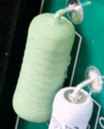
What technology type of resistor are this fat green : metal oxide , wirewound or ... ?
...based on texture ...wirewound for sure but maybe it's important to know the manufacturer....there are many wirewounds...some good .....and some bad.
2cents.😀😎
I'm very interested in this statement:
"The best part is that you can even do this
with amps you have already built, and impress your audio buddies
with the awesome and mysterious power of positive feedback!"
Is there a modification for a stock F5 (F5.7 ?) that would allow me to impress at least myself ? The 6 topologies proposed are not complicated, but not easy to implement in an existing amp.
D.
I think the keyword is the highlighted words. One way to do it on a stock diyF5 it to implement Type 2 of the alternatives on post #442.I'm very interested in this statement:
"The best part is that you can even do this with amps you have already built, ...
Simply :
- install R1 on input
- place an Rsen between ground and Negative speaker terminal
- connect an Rfbp between Jfet gates and Negative speaker terminal
Shouldn't take more than 15 minutes once the parts are ready.
But, it's a different story when someone else built your amp. I'd suggest to take your time and digest the good old 1500+ posts of F5 power amplifier thread.
- Home
- Amplifiers
- Pass Labs
- First Watt F7 review