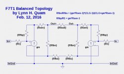
Here is a circuit topology for a balanced (bridged) amplifier using both negative and positive feedback, based on my Type-1 topology. Note that a Type-2 topology cannot be used in a balanced amplifier because the sense resistors are placed between the output load and ground.
Simulations of this topology look very good and should scale well to large amplifiers such as the XA200.8.
Simulations of this topology look very good and should scale well to large amplifiers such as the XA200.8.
Attachments
The best part is that you can even do this
with amps you have already built, and impress your audio buddies
with the awesome and mysterious power of positive feedback!
😎
I am doing this right now with ACA and Input Transformer ..... interesting !!!!
🙂
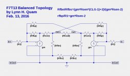
The circuit in post #541 has several problems. The + and - inputs to the amplifier have large voltage swings, due to the feedback topology.
Here is a balanced (bridged) topology that avoids those problems and has inputs to the amplifier that are comparable to those in the unbalanced Type 2 topology.
Here is a balanced (bridged) topology that avoids those problems and has inputs to the amplifier that are comparable to those in the unbalanced Type 2 topology.
Attachments
Last edited:
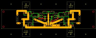
And here is a PCB layout using the DIYAudio Universal Mounting Specification.
Attachments
Last edited:
Looks good, Ilquam. It is a very tempting build. What does the gain look like on this version, is using balanced inputs.
The closed-loop gain is 10X. Yes, balanced inputs to the 3-pin connector at the top middle.Looks good, Ilquam. It is a very tempting build. What does the gain look like on this version, is using balanced inputs.
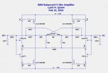
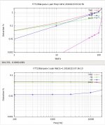
Here is an actual (LTSpice) implementation of the topology of post #542, using double-die ALFETs. It simulates quite well, with THD<1% at over 80W.
Thanks for sharing .
Since the main objective of using positive feedback is to increase the damping factor, can you share what is the DF on your latest circuit.
Fab
Thanks for sharing .
Since the main objective of using positive feedback is to increase the damping factor, can you share what is the DF on your latest circuit.
Fab
The damping factor is around 100 and can easily be changed by minor adjustments to resistors and/or the output FET bias current.
Thanks .The damping factor is around 100 and can easily be changed by minor adjustments to resistors and/or the output FET bias current.
Then you have the same DF as advertised for the F7.
Have you confirmed by simulation that more positive feedback increases DF but also THD?
Is there an important dependency regarding the output impedance of the source feeding the amplifier ?
Fab
More positive feedback increases damping factor, until you reach an optimum value where the internal resistance is zero and the damping factor is infinite. Beyond the point, the damping factor becomes negative and the output level increases with lower output load resistance.Thanks .
Then you have the same DF as advertised for the F7.
Have you confirmed by simulation that more positive feedback increases DF but also THD?
Is there an important dependency regarding the output impedance of the source feeding the amplifier ?
Fab
I have not observed an increase in THD with higher damping factor.
The gain of the balance version is much more usable for your average speakers. In this regard I like the looks of it better. Especially true now that so many folks are doing away with the notion of a preamp and going straight from there source, to the power amp. Since I hope someone will try this. It is very tempting for no other reason then how different it is then your average power amp
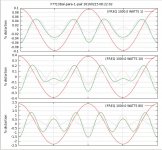
Here are some simulation sweeps and distortion waveforms.
Attachments
Last edited:
While the PCB layout conforms to the UMS, the power dissipation of about 200W/channel requires fan cooling or much larger convection cooled heatsinks. Here is how I accomplished it for a XA30.8 sized amplifier.
Attachments
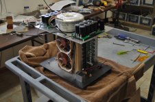
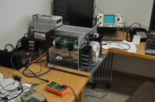
While the PCB layout conforms to the UMS, the power dissipation of about 200W/channel requires fan cooling or much larger convection cooled heatsinks. Here is how I accomplished it for a XA30.8 sized amplifier.
Hello lhquam. Your compact build is impressive. You have put a lot of intellectual and manual power in it; which is admirable, and further evokes pride. Please clarify the following. Textbooks teach that overall negative feedback lowers the input impedance, lowers the voltage gain, and lowers the output impedance of an amp. By contrast, positive feedback does the exact opposite. Why does positive feedback now lower the amp's output impedance?
This balanced amp could be build as mono-blocks and "normal" sized heatsinks and should not require active cooling. It would require obviously a different PCB and two more connections on each board for the positive feedback and the "X" connection. It would be a very simple PCB.
Thanks 2 picoDumbs. It is specific to this special amp.The positive feedback is combined with negative feedback.
- Home
- Amplifiers
- Pass Labs
- First Watt F7 review