Regarding the phase splitter . . .
Any half decent solid state CCS connected to the paralleled cathodes, plus matched plate load resistors, and matched output stage Rg1 resistors, will have as good, or even more balanced signals, than the output tubes plus the output transformer plate taps will balance.
Sometimes it is necessary to slightly un-balance the phase splitter, in order to make up for the un-balanced output tubes and less than perfect output transformer.
But . . . only if you want to null out the 2nd Harmonic.
Do not worry too much . . .
. . . Listen too much!
Last edited:
Yeah, I know. I do have a tendency to 'worry'. Part of it is being 'penny wise' and unknowingly 'pound foolish', part of it is the learning experience and the desire to know what I'm doing.
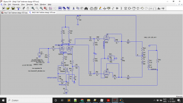
I found a ltspice model (attached) of El Cheapo I've been fooling around with. I adapted it for a transformer model as discussed in a paper (attached) by Menno van der Veen. The transformer values (attached) are from the Amplimo website.
Is the ltspice model any good? What can I learn from it and where does its usefulness end?
Did I adapt the transformer model correctly for use in ltspice?
How to model the UL case? How should I split the inductance and resistance?
Is the ltspice model any good? What can I learn from it and where does its usefulness end?
Did I adapt the transformer model correctly for use in ltspice?
How to model the UL case? How should I split the inductance and resistance?
Attachments
How well matched will the 6AQ5 Quiescent plate+screen currents be?
Un-matched currents causes early saturation and poor bass performance.
Individual 660 Ohm and Individual 100uF in each 6AQ5 cathode, helps to match the plate+screen current, and allows you to measure the 'match' or 'un-match' of the currents.
Un-matched currents causes early saturation and poor bass performance.
Individual 660 Ohm and Individual 100uF in each 6AQ5 cathode, helps to match the plate+screen current, and allows you to measure the 'match' or 'un-match' of the currents.
I'm planning to take the advice of Ketje and split the cathode resistors and caps. Unfortunately I forgot that in the ltspice model.
Since LTspice use the same model for both tubes = two identical tubes, I suppose one or two cathode resistors make no difference.
Except for very low frequencies, the decoupling is easyer with cathodes wired together.
Mona
Except for very low frequencies, the decoupling is easyer with cathodes wired together.
Mona
I indeed found out that the capacitors might need to be increased. But enough about the biasing of the power tubes. What about my initial questions:
Is the ltspice model any good? What can I learn from it and where does its usefulness end?
Did I adapt the transformer model correctly for use in ltspice?
How to model the UL case? How should I split the inductance and resistance?
Is the ltspice model any good? What can I learn from it and where does its usefulness end?
Did I adapt the transformer model correctly for use in ltspice?
How to model the UL case? How should I split the inductance and resistance?
100uF is 80 Ohms capacitive reactance, Xc, at 20Hz.
Start with that value, and then plan accordingly to change the capacitance to what you want Xc to be.
When both cathodes of the output stage use a common resistor and capacitor self bias network, In spice, the issue is when one tube gets near cut off, and or into cutoff, as the other tube current increases (and not linearly).
"Matched Tubes" are not always matched in a given amplifier that has its unique quiescent plate to cathode voltages, screen to cathode voltages, grid to cathode bias voltages, and cathode currents. That is because the match was not tested at those quiescent values.
"All matches are equal, but some matches are more equal than others" - stolen (and modified) from George Orwell, "Animal Farm".
It is those un-matched currents in the push pull output transformers that degrade their performance.
Single Ended output transformers do not care about the current of a single tube, as long as it is well within the transformer's specifications.
"You should make things as simple as possible, but no simpler" - Albert Einstein
I am sorry, I have to leave the simulation software questions to someone else.
LTspice is very useful.
But Software and I do not get along.
Regarding all simulations, I remember the late Bob Pease. He did have some comments over the years.
I hope you settle in on a design, get the parts, and build.
I want to hear how it sounds when you listen.
Happy building and happy listening.
(I expect you will be pleased)
Last edited:
To limit the amount af individual transformers I've selected some candidates that provide B+, B- and heater.
I think I'm going to use toroidal output transformers from Amplimo.
- Netztrafo NTR 1600 | TBT Trafobau 86,90 euro. B+ 250V 260mA & heater 3.5A & 55V 100mA. Standup with end bells.
- Netztrafo NTR 400 | TBT Trafobau 76,30 euro. B+ 250V 400mA & heater 6A & 50V 100mA. Laydown no end bells. End bell: Haube fur Baugrosse M 102 | TBT Trafobau 7,50 euro
- 4N1885 voedingstrafo voor buizenversterkers 103VA 89,00 euro 250V 300mA & 2x heater 2.5A & 50V 100mA.
- 5N1609 voedingstrafo voor buizenversterkers 140VA 95,00 euro 230V 400mA, heater 7A & 40V 100mA
- https://www.ringkerntrafo.nl/shop/h...edingstrafo-voor-buizenversterkers-196va.html 105,00 euro 230V 720mA, 2x heater 2A & 50V 100mA.
Standup (NTR1600) might be preferred for limiting coupling of 50Hz into the output transformers.
NTR400 can delivered a lot more current. Might not be strictly needed, but a bit of overdimensioning might be a good idea? In same plane as OT: problem?
And then several toroidal power transformer options with increasing currents. Are toroidal power transformers 'ok'? Do they couple to the OT's as they lay in the same plane? Or is their leakage that low that it doesn't matter?
It might not be the most 'El Cheapo' options, but absolute lowest cost is not a goal.
Edit: I plan on using 6V6's and replacing the 12al5 with diodes so only 6.3V heaters are needed. Will add protective diodes to grids of the 12AT7.
Last edited:
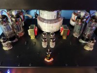
Toroidal transformers are excellent with very low leakage flux and I've hever heard any of mine hum. And you can stack them if you need more chassis real estate.
The Hammond 278CX I have sounds like an electrical substation it hums so much LOL
The Hammond 278CX I have sounds like an electrical substation it hums so much LOL
Attachments
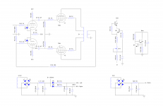
Update: schematic with some changes.
- I think I've got some volts to give away, so I increased the 100R dropping resistors to 1k.
- Changed some power supply caps. Some smaller because of availability, others larger because the rectifier tube is replaced by SS diodes.
- Protective diodes on the 12AT7's
- (Option of) bias a la Baby Huey, as a result of 6A3sUMMER's remarks (if I interpreted those correctly).
- Input to be decided (be patient 6A3sUMMER ;-) )
- Bridge rectifier as the secondary voltages are different
- Lowered the LTP tail resistor because of the lower voltage.
- CL120's to be added.
Attachments
Tom,
I like your idea to use the diodes on the input tube grids.
During Hot-Start conditions (power is on, goes out, comes back on; the current sink can dump all that current from the cathode to the grid (if the plate B+ voltage is collapsed).
Think about this:
Switch the positions of the 500uF and 220uF B+ caps.
It will do 4 good things:
1. Make the 270V winding run cooler.
2. Reduce the inrush current during Power-Up.
3. Make the B+ that runs the output stages a much lower impedance.
4. May allow a smaller fuse in the transformer primary power mains circuit
(because of the lower power-up inrush current).
You are going to fuse the primary, Yes?
I hope so.
And, I do not see any bleeder resistors on the power supplies.
Prevent the "Surviving Spouse Syndrome" Use bleeder resistors.
Safety First!
Last edited:
@Tom Kamphuys
How good is your test bench? Do you own an o'scope and signal generator? After you get the amp working (sort of), you can experiment with phase compensation. Feed a 2 KHz. square wave to the I/P and try various small capacitances in parallel with R14. Examine the waveform across your "dummy" resistive load. Settle on a value that yields the best "look". Some compromise among overshoot, ringing, and tilt is inevitable.
If the available test equipment is limited, we'll fall back on a brute force method of phase compensation.
Ok, I took the advice (see attachement).
I do have an oscilloscope, an old Philips. Bought it second hand for 25,- euro or so. Turned out it used to be of the university I went to; we might have met before. And a somewhat decent multimeter and an el cheapo one.
I've been looking at a pico scope, but recently my interest has moved to an analog discovery 2 (+ audio analyzer suite). Is that the full audio test set it seems to be? Is it any good?
Attachments
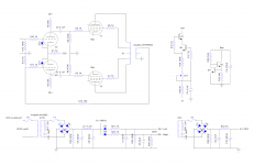
The B+ 1k resistors and 50uF caps that powers the input phase splitter tubes . . .
That is -3dB @ 3.2Hz, plenty good!
But that makes me think that D5 and D6 are not needed.
The 1.5k and 10nF have a pole frequency of 10kHz.
Unless you live near US Navy's Megawatt 15kHz transmitter, or a Loran 60kHz transmitter, or similar Very Low Frequency transmitters, those RC snubbers are probably not needed.
I have always fused the transformer primary. I have not fused the transformer secondary.
But here is an idea you might find useful to protect your amplifiers:
In the primary circuit, I use 2 Fuses in Series.
1. A Fast Blow Fuse that has an Amp rating that does not blow out during the Power-Up of the amplifier.
(Inrush current that is caused by the Un-charged B+ caps, and by the very low resistance Cold Filaments).
2. A Slow Blow Fuse that has an Amp rating that does not blow out during the loudest sustained music passage that you playback.
These 2 fuses in series give protection for a number of different kinds of amplifier faults that cause excess current draw.
For example, I have a low power mono-block amp that has a Fast Blow 1 Amp fuse, in series with a 0.5A Slow Blow fuse.
Of course, you start with low Amp ratings, they blow, and you try the next higher Amp rating, and see if that is enough.
Last edited:
In the primary circuit, I use 2 Fuses in Series.
1. A Fast Blow Fuse that has an Amp rating that does not blow out during the Power-Up of the amplifier.
(Inrush current that is caused by the Un-charged B+ caps, and by the very low resistance Cold Filaments).
2. A Slow Blow Fuse that has an Amp rating that does not blow out during the loudest sustained music passage that you playback.
These 2 fuses in series give protection for a number of different kinds of amplifier faults that cause excess current draw.
For example, I have a low power mono-block amp that has a Fast Blow 1 Amp fuse, in series with a 0.5A Slow Blow fuse.
Of course, you start with low Amp ratings, they blow, and you try the next higher Amp rating, and see if that is enough.
Me like!
 🙂 The concept needs to be disseminated.
'Mot du jour': disseminated. Eli, are you by any chance a health care professional? prophylaxis, hemostat, disseminated...
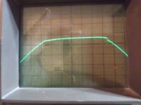
I placed the snubber to limit the 'switching noise'. See attachement of a scope image just after the power transformer (using UF5408 rectifier).
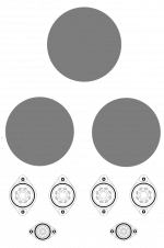
And what are your comments about the two layout examples?
I placed the snubber to limit the 'switching noise'. See attachement of a scope image just after the power transformer (using UF5408 rectifier).
And what are your comments about the two layout examples?
Attachments

Eli, are you by any chance a health care professional?
I'm a retired computer programmer. I was educated as a Chemist.
Not much difference, just rout the PT wires away from both OT and sensitive circuitry as that part of the toroid has the most leakage. Solder the UF5408 close to / straight on the PT and keep the reservoir elco very close, as much out of the way of mentioned circuitry.what are your comments about the two layout examples?
EL84 does not give much heat, otherwise I would opt for the first possibility.
6A3sUMMER said D5 and D6 might not be needed with the 1k dropping resistors. I've thinking about and simulating their function. I think I read somewhere they are there to decouple the two source voltages of the two 12AT7's. But as the current draw is controlled by the current source to a steady 6-7mA I don't see how they would steal voltage from the other channel. Still, the power tubes could steal some voltage from the 12AX7's. I haven't figured out how to simulate that, but I would only need one diode (and one bleeder resistor) to stop that from happening.
Is my reasoning correct, or am I missing something?
Is my reasoning correct, or am I missing something?
- Home
- Amplifiers
- Tubes / Valves
- First stereo tube amp build advice