My google information bubble has exploded. Using your direct advice and casual remark has led me to a wealth of books, articles, websites and papers.
I have quite some reading todo. Guitar tube amp are quite different from hifi tube amps. I knew that, but hadn't realised it to the full extend.
I have quite some reading todo. Guitar tube amp are quite different from hifi tube amps. I knew that, but hadn't realised it to the full extend.
Menno van der Veen's designs test and listen very well. He has published much of his thinking. This was "new" about 30 years ago but is no longer very controversial.
Home
About
Publications
Many thanks for the links.
Layer wounding, pied windings, parallel bifilar windings, wire over wire winding couldn't be applied to toroids. Its so much more in audio transformer winding, maybe he found a different way to optimize.
He is still an outsider in his business. Many outsiders exist in high end audio, because their ideas are believable.
I just can say that the majority of audio transformers have done it a different way, the conventional way. I'm not going to follow his route, because all the best transformer companies of today choose a different way.
If 99 car drivers drive in one direction and only one chosses the opposite direction, thats not an argument for me that his ideas are being no longer controversial.
If he would have found a golden way of improving in output transformers by winding on toroids (which is much more easy compared to the methods described above) than many companies would have followed him.
His followers are only a very small group, mostly all of them use toroids to manufacture cheap transformers.
No one of the high end manufacturers followed his ideas. Mostly they follow my ideas of good transformer winding practice.
Last edited:
I've got lots of question, but I'll limit myself to a few. Here they are: What amp do you guys suggest I should build? Are there any informative build threads or sites? Any must read books, articles or websites? I've read both tube preamp book by Merlin Blencowe and the power amp book by Richard Kuehnel.
Morgan Jones, "Valve Amplifiers".
I'd start with a sweep tube spud. You can build one for a few hundred bucks.
Tubelab and Pete Millett are good places to start. Or just read this forum for a while... 🙂
Tom
After switching back and forth between the El Cheapo and Baby Huey and thinking I might pick the best of both, I've come to the conclusion that the El Cheapo was designed by smart people and discussed extensively (very unfortunately the original thread is nowhere to be found). Who am I to improve on it?!
So, El Cheapo it is. I'm gathering as much info as I can find and have started to put it into one document; currently mostly quotes of Eli Duttman. It is a way for me to bundle the scattered info. Thinking big: We might even construct a dedicated El Cheapo site. Who knows...
In that process I looked at the 12AL5. It is hard to find and of my go to shops, only one has 'm and is charging 20,00 euro. Quite a lot w.r.t. the 12AQ5 ($4 or 8,- euro). Is the slow start needed? Are there other ways to provide the slow start?
And I wonder: How is the LTP biased?
Last edited:
A negative voltage supply is necessary to place a constant-current sink in the 'tail' of the long-tailed pair ("LTP"). That's what makes the 'tail' 'long', you see? The bigger the impedance in the tail of the LTP, the better.
There are all sorts of devices you can use to create that large impedance, or if you're absolutely against using any silicon in a tube amp, you can use a bi-polar power supply (say +/-320V) and use a big honkin' resistor to burn off 322V so there's an approximately +2V DC bias at the cathodes of the 12AT7 (ECC81) LTP.
If you're familiar with the phase splitter in the classic Fender or Marshall tube guitar amps, you're familiar with an LTP. The 'Schmitt inverter' is actually a form of AC-coupled LTP, otherwise known as a 'cathode-coupled phase splitter'.
Check this out. It's an explanation of how the Schmitt inverter works in a Fender or Marshall tube guitar amp:
The Valve Wizard -Long Tail Pair
Rt is the 'tail'. You could put a CCS there instead of the resistor, which would improve the push-pull balance of the outputs.
Here's another explanation of the AC-coupled LTP as used in Fender and Marshall guitar amps.
The Long-Tail Pair
This is the DC-coupled version of the LTP, as found in the old Mullard 5-20 amplifier:
The Valve Wizard
Last edited:
In that process I looked at the 12AL5. It is hard to find and of my go to shops, only one has 'm and is charging 20,00 euro. Quite a lot w.r.t. the 12AQ5 ($4 or 8,- euro). Is the slow start needed? Are there other ways to provide the slow start?
In any event, you have to rework the negative supply. The Allied 6K27VF transformer works only in North America.
Can a you economically source a 6AL5/EAA91? If you reduce the value of the CF resistor between the LTP cathodes and CCS, the voltage of the B- rail can be smaller. Remember, severe budgetary constraints drove the project's development. A low cost low voltage toroid transformer could be 1/2 wave parallel multiplied to obtain the rail and the twin diode (with its sections in parallel) used only as a delaying device.
As for the 12AQ5, it was chosen as a low cost member of the 6V6 "clan". Any 6V6 family type will work. Possibilities include: (of course) 6V6, 6CM6, 6AQ5/EL90, 7C5, and 12AB5.
Attachments


The 6AL5 is €13,-. Actually, the cost is not a problem; I hate heater wiring . I am searching for more expensive transformers with end bells, just because I don't like the naked transformers. Quite a journey to find the iron.
Would it be a possibility to use the protection diode per valve wizard?
Would it be a possibility to use the protection diode per valve wizard?
Attachments
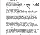
I think the diode is present to prevent the grid from becoming too positive wrt the cathode resulting in arcing and tube death.
This situation arises during start-up (using ss rectifiers) for dc coupled cathode followers as you and valve wizard say.
However, I think, with my limited knowledge, that the same situation (grid too positive wrt cathode) arises during start-up in the El Cheapo. The slow start B- diode enables the 12at7 to heat up and start conducting thereby 'solving' the problem. I think it is a relative problem. Whether the grid goes up too fast or the cathode down too fast, arcing might occur. Same problem, same solution?
I'm a bit too stubborn to just believe statements without an explanation. Sorry.
With DC-coupled designs you have full B+ at the second tube's grid and ground potential at its cathode during the startup, when tubes are cold and don't conduct yet.
All grids in El-Cheapo are always at the ground potential in terms of DC, being tied to the ground by grid leak resistors and having all possible DC voltages blocked by the coupling cap - amp being off or on, powering up or shutting down, doesn't matter.
All grids in El-Cheapo are always at the ground potential in terms of DC, being tied to the ground by grid leak resistors and having all possible DC voltages blocked by the coupling cap - amp being off or on, powering up or shutting down, doesn't matter.
Yes, the 'T7 grids are at ground potential. However, an "instantaneous" on/SS rectified B- rail will result in the grids being positive WRT the cold cathodes. Once emission and conduction start, the CCS forces the grids negative WRT to the cathodes. I took no prisoners and "soft" started the B- rail. RES charges $4 for a 12AL5/UAA91 and $3 for a 6AL5/EAA91.
Perhaps a costly OS small signal tube that exhibits the notorious Philips flash would be safe. FWIW, I've seen it said that Philips developed the heater flash to have tubes which mate well with directly heated/fast starting vacuum rectifiers, like the 5U4. Whether the tale is true or not, I don't know.
Perhaps a costly OS small signal tube that exhibits the notorious Philips flash would be safe. FWIW, I've seen it said that Philips developed the heater flash to have tubes which mate well with directly heated/fast starting vacuum rectifiers, like the 5U4. Whether the tale is true or not, I don't know.
For your first amp build I would not choose direct coupling. A capacitor will also make testing and fault finding of input and power stages simpler.
Just spotted this thread, I'm going through the same but with OTL and low impedance headphones.
One interesting amp I've seen is the Brazilian OTL and the update/errata:
OTL: Brazilian OTL
Update/Errata:Brazilian OTL Update & BCF
If you ignore the back end and look at the driver and forward - you'll see an LTP with a triode acting as a CCS.
I put the design into LTSpice and it seems to work nicely including having (a) nicely balanced output from the LTP, (b) global feedback with step capacitor etc plus (c) solid state back end to help current delivery. (a)&(b) lower impedance further from my understanding:
View attachment Brazilian OTL.asc
I forgot this version has DC servo on the bias with a set bias on one side. This doesn't cover the Vcathode-header limitations that some tubes have and should one arc - there's no crowbar on the output.
Last edited:
This was the first amp I built. It was a very nice amp if you don't mind the floating paraphase inverter. I went with separate 250R cathode resistors for the finals each with their own 330u cap. I also used SS rectification.

I think Eli in principle agrees with my reasoning. Are there any drawbacks to the diode?
I think I recall from the posts I've read, the tube is also free of 'hash' caused by ss diodes? Did I remember that correctly?
I think I recall from the posts I've read, the tube is also free of 'hash' caused by ss diodes? Did I remember that correctly?
A vacuum rectifier can block SS diode switching noise. A signal tube or transistor is most definitely vulnerable to said noise riding on a power rail.
A negative voltage supply is necessary to place a constant-current sink in the 'tail' of the long-tailed pair ("LTP"). That's what makes the 'tail' 'long', you see? The bigger the impedance in the tail of the LTP, the better.
There are all sorts of devices you can use to create that large impedance, or if you're absolutely against using any silicon in a tube amp, you can use a bi-polar power supply (say +/-320V) and use a big honkin' resistor to burn off 322V so there's an approximately +2V DC bias at the cathodes of the 12AT7 (ECC81) LTP.
If you're familiar with the phase splitter in the classic Fender or Marshall tube guitar amps, you're familiar with an LTP. The 'Schmitt inverter' is actually a form of AC-coupled LTP, otherwise known as a 'cathode-coupled phase splitter'.
Check this out. It's an explanation of how the Schmitt inverter works in a Fender or Marshall tube guitar amp:
The Valve Wizard -Long Tail Pair
Rt is the 'tail'. You could put a CCS there instead of the resistor, which would improve the push-pull balance of the outputs.
Here's another explanation of the AC-coupled LTP as used in Fender and Marshall guitar amps.
The Long-Tail Pair
This is the DC-coupled version of the LTP, as found in the old Mullard 5-20 amplifier:
The Valve Wizard
I'm familiar with all of that. I miss the bias resistor (and the grid leaks) in El Cheapo though.
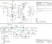
You don't need that 12AL5 nor the transformer that go with it.Makes it still cheaper (El extra Cheap 😉 )
Just steel 5V from the HT (not much difference 350V or 345V).
No high negative voltage, no risk for the 12AT7 grid.
Bonus, no current adjust.
I decoupled the cathode resistors of the finals, I don't like the common resistor solution.
Mona
Just steel 5V from the HT (not much difference 350V or 345V).
No high negative voltage, no risk for the 12AT7 grid.
Bonus, no current adjust.
I decoupled the cathode resistors of the finals, I don't like the common resistor solution.
Mona
Attachments
- Home
- Amplifiers
- Tubes / Valves
- First stereo tube amp build advice