Hi everyone, this is my first post, and my first project. Please be patient with my newb questions.
First up, sorry if this is posted in the wrong forum, please let me know where to post it if so.
So i have no experience at all in speaker design or building, and only middling experience in electronics. However, ive been interested in taking on a project for a long time and have been watching youtube vids/collecting gear like soldering iron etc for about a year now.
A few weeks back, i found a retro style radio for sale at a garage sale. I decided to make this my first project. This is intended to be a bluetooth speaker system for my workshed. I want it to have bluetooth radio and AUX functionality with a remote control. So I stripped out the old electronics, and cleaned up the shell. (cleaner than whats shown in this pic anyway)
I bought a bluetooth decoder with FM, Aux and USB functionality on ebay.
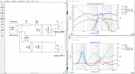
I then went to do the quick job of making some speakers for it.... Oh bless past my innocence.... 3 weeks later, countless hours on youtube, a few tutorials and 3 programs later, i have this:
Now, like i said, i have zero experience, and am just learning what i can on the fly. But, i think if ive understood everything correctly, what i have here should work? I figured id hop on here and ask you guys what your opinion was before i fork out several hundred dollars on making it happen.
FYI, this is the tweeter i plan on using:
ND28F-6 1-1/8" Neodymium Dome Tweeter 6 Ohm - Dayton Audio
And here is the woofer im looking at:
TCP115-4 4" Poly Cone Midbass Woofer 4 Ohm
Im planning to make 2 closed speaker boxes out of MDF, (one woofer and one tweeter in each). one for each side of the radio case, and mount my bluetooth thingo in the middle. Put some nice cloth in front of the speakers to keep with the retro asthetic. etc etc.
My biggest question right now is the 2400uF capacitor on the woofer. I am given to understand that ususally, you want to stick with film capacitors in stereo design. However, obviously a film capacitor of that size would be prohibitivly expensive. This video seems to claim that if you have a large electrolitic capacitor in series with a resistor, and those in parralel with a film capacitor, then it should be fine.
YouTube
Now im pretty sure that describes what i have in the above schematic. Can anyone confirm for me please if the above system will work with an electrolytic capacitor in the 2400uF position. If not, what are my alternatives?
Many thanks everyone
First up, sorry if this is posted in the wrong forum, please let me know where to post it if so.
So i have no experience at all in speaker design or building, and only middling experience in electronics. However, ive been interested in taking on a project for a long time and have been watching youtube vids/collecting gear like soldering iron etc for about a year now.
A few weeks back, i found a retro style radio for sale at a garage sale. I decided to make this my first project. This is intended to be a bluetooth speaker system for my workshed. I want it to have bluetooth radio and AUX functionality with a remote control. So I stripped out the old electronics, and cleaned up the shell. (cleaner than whats shown in this pic anyway)
An externally hosted image should be here but it was not working when we last tested it.
I bought a bluetooth decoder with FM, Aux and USB functionality on ebay.
An externally hosted image should be here but it was not working when we last tested it.
I then went to do the quick job of making some speakers for it.... Oh bless past my innocence.... 3 weeks later, countless hours on youtube, a few tutorials and 3 programs later, i have this:
An externally hosted image should be here but it was not working when we last tested it.
Now, like i said, i have zero experience, and am just learning what i can on the fly. But, i think if ive understood everything correctly, what i have here should work? I figured id hop on here and ask you guys what your opinion was before i fork out several hundred dollars on making it happen.
FYI, this is the tweeter i plan on using:
ND28F-6 1-1/8" Neodymium Dome Tweeter 6 Ohm - Dayton Audio
And here is the woofer im looking at:
TCP115-4 4" Poly Cone Midbass Woofer 4 Ohm
Im planning to make 2 closed speaker boxes out of MDF, (one woofer and one tweeter in each). one for each side of the radio case, and mount my bluetooth thingo in the middle. Put some nice cloth in front of the speakers to keep with the retro asthetic. etc etc.
My biggest question right now is the 2400uF capacitor on the woofer. I am given to understand that ususally, you want to stick with film capacitors in stereo design. However, obviously a film capacitor of that size would be prohibitivly expensive. This video seems to claim that if you have a large electrolitic capacitor in series with a resistor, and those in parralel with a film capacitor, then it should be fine.
YouTube
Now im pretty sure that describes what i have in the above schematic. Can anyone confirm for me please if the above system will work with an electrolytic capacitor in the 2400uF position. If not, what are my alternatives?
Many thanks everyone
Attachments


Electrolytic capacitors get a bad rap, but they aren't as bad as that.
Anyway, remove it altogether. The 2400uF value means that it is acting like a piece of wire at audio frequencies.
Anyway, remove it altogether. The 2400uF value means that it is acting like a piece of wire at audio frequencies.
Thanks AllenB. Tried that, and like you said, made no difference to the overall graph. I guess that was an easy fix 🙂
Does everything else look good to go?
Does everything else look good to go?
I would probably start by trying to ditch the remaining woofer resistor. This will take some adjustment of the other two components to restore the balance. This should take the impedance back above 2 ohms.Does everything else look good to go?
What are your Voltage and current requirements for each component?how do i choose a amplifier and power source for the proposed system?
I would probably start by trying to ditch the remaining woofer resistor. This will take some adjustment of the other two components to restore the balance. This should take the impedance back above 2 ohms.
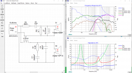
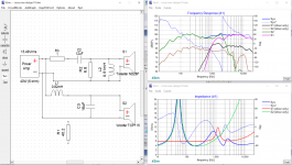
Thanks again for your advice. I tried taking away the resistor, but it creates a HUGE spike in the impedence @ 53 Hz (Image 1). I couldnt seem to reduce that spike with the other components. So I tried adjusting the resistor's value and adjusting the other components until i had a minimum impedence of 4 Ohms (image 2). Im worried that the impedence graph is still too variable.
1. What is the minimum impedence i should be aiming for?
2. How much variability is acceptable in the impedence graph?
3. What other options do i have?
What are your Voltage and current requirements for each component?
Had to use a website to calculate the current and volts from the watts and impedance, but here we go
Tweeter:
Impedance: 6 Ohms
RMS: 30 watts
Current: 2.23606798 amps
Voltage: 13.4164079 V
Woofer:
Impedance: 4 Ohms
RMS: 40 watts
Current: 3.35410197 amps
Voltage: 13.4164079 V
Attachments

Why don't you like this?it creates a HUGE spike in the impedence @ 53 Hz
I thought you wanted to power the bluetooth frontend?Had to use a website to calculate the current and volts from the watts and impedance, but here we go
Is there a reason you cannot use a normal audio amplifier or is that ok?
I was under the impression that the impedence graph should be as close to flat as possible?
The bluetooth device is 5V, not sure what current it uses. Ill get my altometer out tommorrow to check. Honestly, ive not really looked at different amplifiers at all yet. I figured id design the speakers first, and get an amp/power supply that suited it after i knew what i needed.
The bluetooth device is 5V, not sure what current it uses. Ill get my altometer out tommorrow to check. Honestly, ive not really looked at different amplifiers at all yet. I figured id design the speakers first, and get an amp/power supply that suited it after i knew what i needed.
I think you should look at a vaguely similar well-executed project for an idea that might work:
Eekels' Mini
Basic circuit should work with most 4" plus 1" drivers. And it does everything that is good here. You always get an impedance peak on the bass, whether closed box or reflex.
FWIW, you have selected a Qts 0.35 woofer more suited to reflex, which means you have a port in the cabinet. About 5L, I'd guess based on a Vas of 3.1L.
Last edited:
To deal with this you can use a Voltage source amplifier. Typical audio amplifiers are like this. They are designed to ignore these impedance variations (sort of).I was under the impression that the impedence graph should be as close to flat as possible?
Ok, if it already has a supply then we don't need to measure that one.The bluetooth device is 5V, not sure what current it uses.
I was under the impression that the impedence graph should be as close to flat as possible?
You will almost always have a rise in impedance at the woofer's resonant frequency and sometimes at crossover points. Rising impedance is generally NOT a problem.
The time to worry is when you get deep dips in impedance, below your target. Those can become an amp-killer.
"I was under the impression that the impedence graph should be as close to flat as possible?".
I don't understand the purpose of the CR network across the woofer at all, but I agree with AllenB that it will be a S/C at audio frequencies.
That network although the same in structure, does not look like a Zobel netork.
In any case I have very strong reservations about the need for a Zobel network.
It is argued that one is necessary in order to present a relatively constant Z to the amplifier, but it only really matters if the Z dips to low values placing high current demands on it. What does it matter if the Z goes up to 750 ohms at 1KHz for eg? That will help the amplifier.
I have used just an L in series with my mid/woofer, to flatten its FR characteristic. I don't care that it has a very high Z above the Xover, this serves to lower the load and hence stress on the amplifier.
The loading of the 3.8 ohm resistor will only cause a higher current to be drawn from the power amp; what advantage does that have?
That Eekel's Mini suggestion was a serious one:
Eekels' Mini
But is rather sophisticated.
An off-the-shelf crossover is this one:
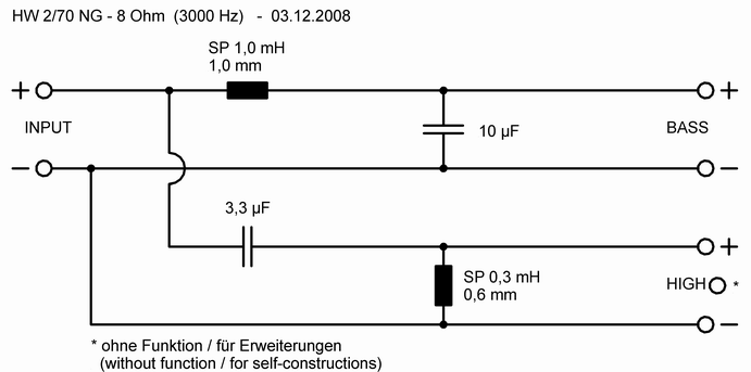
HW 2/70 NG - 8 Ohm | Visaton
Add a couple of attenuating resistors for tweeter level and it looks quite good for a 4 ohm bass IMO. You can design for flat impedance, but this is something that mostly interests the SET (single ended triode) valve enthusiasts.
Cheaper regular HiFi voltage feedback amplifiers dislike low impedance at high phase angle. Typically reflex designs at 4 ohms. They run out of current. High impedance bothers them not at all.
Eekels' Mini
But is rather sophisticated.
An off-the-shelf crossover is this one:
HW 2/70 NG - 8 Ohm | Visaton
Add a couple of attenuating resistors for tweeter level and it looks quite good for a 4 ohm bass IMO. You can design for flat impedance, but this is something that mostly interests the SET (single ended triode) valve enthusiasts.
Cheaper regular HiFi voltage feedback amplifiers dislike low impedance at high phase angle. Typically reflex designs at 4 ohms. They run out of current. High impedance bothers them not at all.
Last edited:
.
The loading of the 3.8 ohm resistor will only cause a higher current to be drawn from the power amp; what advantage does that have?
Basically any current passing through a crossover that does not go through a voice coil is wasted energy... something to be avoided if you want efficient speakers.
Exactly Douglas, to be avoided in any case.
System7, I still have in the loft, a crossover of that form made in 'about '67 in my apprenticeship; I didn't think that they were still used, let alone advocated.
System7, I still have in the loft, a crossover of that form made in 'about '67 in my apprenticeship; I didn't think that they were still used, let alone advocated.
Thanks for the clarrification on the impedence graph guys. Helps heaps to know i dont have to be so precious about that.
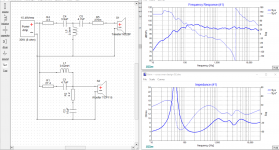
@System7 Thanks for the reccomendation. I took a look, and put that crossover diagram into XSim (Image 1). Obviously it was less than ideal for my drivers at the given values, but after some tweaking, i think i have it looking ok (Image 2). Is that functionally going to any better than the other setup I had? (Image 3). Should i just go for the cheaper setup at this point?
@Pharos, You clearly know alot about what your talking about and i appreciate your input. However, I really dont know alot about what im talking about. Can you please clarify what you mean in simpler terms? I can't see a 3.8 Ohm resistor anywhere on my schematic.
@AllenB Is there a good amplifier you could reccomend me, or perhaps a guide on how to choose one? Again, I really dont know alot about this, but im happy to invest the time required to learn.
Thanks again guys.
Attachments

Unless you have bought the woofers already, I think the 8 ohm version of this paper cone will just be easier: TCP115-8 4" Treated Paper Cone Midbass Woofer 8 Ohm
Your 4 ohm driver is not a polycone according to Dayton Audio:
TCP115-4 4" Poly Cone Midbass Woofer 4 Ohm
From what I see of the tweeter, it needs quite a high crossover, around 3kHz:
Dayton Audio ND28F-6 1-1/8" Soft Dome Neodymium Tweeter
So smaller values like 4.7uF and 0.2mH ought to do the right things. The tweeter has quite a sharp impedance peak around 1kHz, so a 10R resistor in parallel with it will be no bad thing.
The bass filter is usually just a coil and capacitor. Simple as that.
I am a bit mystified by the downward slope on the bass driver, and I wonder how Dayton have measured it. Always a headache with imported files to know how hey were measured. In a box or on a big baffle?
The bass breaks up a bit above 5kHz, so hope for the best.
If I told you all my amplifier biases I'd be here all day. There's one thing you should know first.. as amplifiers of different types get closer to perfect performance, they begin to sound the same as each other. It's important to remember this so you don't accidentally aim for the moon. Just stick with solid performance.@AllenB Is there a good amplifier you could reccomend me, or perhaps a guide on how to choose one? Again, I really dont know alot about this, but im happy to invest the time required to learn.
Are you interested in accuracy or do you want something with special distortion features. Are you buying or building, if building have you done it before?
Some would suggest a class A amplifier for efficient speakers or low level listening. Have you an opinion?
@system7 Thanks, just subbed in that woofer. Looks like i can get a decent crossover quite a bit cheaper (Image 1). Also should have a minimum of ~8.4Ohms impedence. Which, since i gather higher impedence is better makes this a significant upgrade on my last setup?
@AllenB I dont think i need any distortion features? This is for my garage/workshed, so it doesnt need to be crazy, and I am on a budget, so going somthing with solid performance, should be good.
In terms of building or buying an amp, I dont know whats involved in building one. Given im already pretty far out of my comfort zone with this project, Im probably just as happy to buy one provided the price is right. How difficult is it to build one?
Attachments

Which, since i gather higher impedence is better makes this a significant upgrade on my last setup?
Sorry to but in again ... but higher doesn't mean better. It is a little easier on the amplifier because it draws less current, but that's about the only advantage.
"Better" generally comes from carefully matching drivers and box designs. In theory, the right drivers in the right box don't need a complex crossover. Sometimes it can be as simple as a single capacitor to keep bass energy out of the tweeter.
The crossover does play a role, of course, but mostly it's there to correct for our compromises.
What I meant by my previous post is that if you are doing a design and you get a real low dip in impedance someplace on the response curve, it could overheat and damage the amplifier... That is if you are designing for 8 ohms and at some point the impedance dips to 1 ohm, even while the rest is still at 8 or 10 ohms, your amp is at risk.
The opposite... that characteristic rise to 20 ohms or so at woofer resonance is not harmful. It's just hard to look at. 😀
- Home
- Loudspeakers
- Multi-Way
- First project - Will this crossover design work?