@Douglas Blake
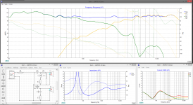
If i understand your comments, your main concern with most of the proposed designs are about different components drawing too much current yes? I had a play around with XSim just now, and found where to bring up the current graph. What should I be aiming for? the improved current graph you posed showed the currents of the devices changing throughout, but never going above 4Amps. Is this the aim? Or is the shape of the curve important too? For example, here is the current from the last CO design i did. (I havnt yet updated it for all the new advice you wonderful people have given). The current stays below 3 the whole way, but the curves do not have the same shape as the ones in your graph. Is that a problem?
If i understand your comments, your main concern with most of the proposed designs are about different components drawing too much current yes? I had a play around with XSim just now, and found where to bring up the current graph. What should I be aiming for? the improved current graph you posed showed the currents of the devices changing throughout, but never going above 4Amps. Is this the aim? Or is the shape of the curve important too? For example, here is the current from the last CO design i did. (I havnt yet updated it for all the new advice you wonderful people have given). The current stays below 3 the whole way, but the curves do not have the same shape as the ones in your graph. Is that a problem?
@waxx
Thanks for you working on the design of this, i dont understand alot of the technical terms being said, but im learning fast, thanks for taking the time to help me.
Thanks for you working on the design of this, i dont understand alot of the technical terms being said, but im learning fast, thanks for taking the time to help me.
If i understand your comments, your main concern with most of the proposed designs are about different components drawing too much current yes?
That is one of the concerns. Any currents flowing that don't go through a voice coil are simply wasted energy. We should naturally want to minimise that as it makes our speakers less and less efficient. In some cases it can actually damage a very expensive amplifier.
Have a look at my commentary in THIS THREAD Also in earlier messages here you will see where I've pointed out some issues where more than half of the amplifier's current is simply wasted in overly complex filter designs.
I had a play around with XSim just now, and found where to bring up the current graph. What should I be aiming for?
Ideally ALL current from the amplifier should go through a voice coil. The goal is to minimize wasted energy as much as possible.
If you post your DXO file I will be happy to have a look at it and give you my suggestions.
Higher frequencies shouldn't receive full amplifier output in any case, so reading the sim directly will be misleading. Music has more energy focussed around the fundamentals at lower and middle frequencies.but never going above 4Amps.
Attachments
That is one of the concerns. Any currents flowing that don't go through a voice coil are simply wasted energy. We should naturally want to minimise that as it makes our speakers less and less efficient. In some cases it can actually damage a very expensive amplifier.
Have a look at my commentary in THIS THREAD Also in earlier messages here you will see where I've pointed out some issues where more than half of the amplifier's current is simply wasted in overly complex filter designs.
Ideally ALL current from the amplifier should go through a voice coil. The goal is to minimize wasted energy as much as possible.
If you post your DXO file I will be happy to have a look at it and give you my suggestions.
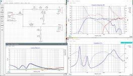
Even if i think that you made some mistakes in your calculations (tweeter frequencies will never give full power), your general point is true. When i build a crossover for real this is a factor i study more than here. Here it was first trying to understand what other said, and then try to apply the techniques explained. But i gave it a go with your remarks in mind...
This sim is with the R5 like you use it (to measure the current going in) and the drivers are shown in the current graph. I loose some current because the attenuation of the tweeter, but for the rest it's optimised now i think...
Attachments
You might get it a bit closer by tweaking C2 and R1 a bit... C2 at 16uf and R1 at 4.7 ohms evens the midrange out a bit. It's not likely to make a huge difference in what you hear but it would reduce the wasted current a bit.
Those are some gnarly drivers, my friend... you're lucky you got it where it is.
Those are some gnarly drivers, my friend... you're lucky you got it where it is.
Those are some gnarly drivers, my friend... you're lucky you got it where it is.
I know, i have to work hard to get here. But it's a challenge and a good time passing in the Corona lockdown we have here in Belgium...
And to everybody who posted here and criticised my versions, thank you a lot, i learned a lot by doing this and reading and discussing your remarks. And thanks to the OP for setting up this project. You can off course use my work. I got paid in a lot of knowledge and advice for it... 😀
Blake, I'm trying to figure out if looking at the current draw at 100W fails to give the whole picture in this example with the OP's chosen drivers. Here's what I mean.
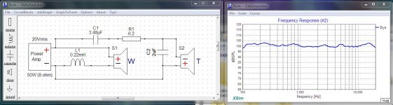
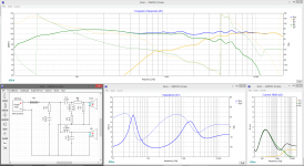
Assuming you've got a 100W amplifier at 4ohm, that means it's capable of a max current of 5 amps (Current = the squareroot of Power over Resistance). Now with the TCP115-4, according to the spec sheet and Unibox, xmax with musical content above 40Hz will be reached with 6W for an SPL of 90.5dB at 1m. Let's assume that we turn the volume knob up a little more with it anyways and that maybe we want to give 3dB more for headroom and so the maximum power we will be pulling from the amplifier is 20W. I think that's fairly realistic. Heck the max power rating of the driver is only 40W anyways.
In the XSim below, using the xo I designed in Post #25, now if we look at the current draw with the maximum of 20W that we are likely to ever use, we see that the speaker never actually draws more than 4amps from the amplifier. And in fact the highest current draw from this design is at about 200Hz which has nothing to do with the xo and everything to do with the inefficiency of the driver.
My conclusion would therefore be that it's a completely acceptable xo for these drivers as long as we have enough power (and current) to drive them. Indeed it reinforces the need for a high current amp and therefore perhaps the need for a little more watts than one might think if you are just looking at the sensitivity, max SPL and power relationship. And the need to be careful with component values in your parallel xo legs as well I guess.
Attachments
Good to see you back Mygyth. Good to hear you are still working in these crazy times too!! 😱
A quick search suggests power tools are in the range of 90-100dB. That's going to be hard to exceed with such a small woofer (and your ears probably don't want you to do that for any extended period of time) but with 2 of the TCP115-4 you will be able to to play music to about 87-90dB when you are about 2m away and if they are placed up against a wall so that you don't lose a full 6dB to baffle step loss.
If you want louder than that you'll need larger drivers or multiples of the small ones and so bigger boxes either way. Up to you to decide what's best for you. I'd probably go ahead with the bluetooth radio idea because it's kind of cool and not too expensive and then I'd maybe see whether or not it will play loud enough in your workshed.
Anyway, now that I have those radio measurements, I can work up some new diffraction sims and then come up with a more accurate xo if you like. Or I can post the frd and zma files I come up with and you can try your hand at the xo work yourself.
My conclusion would therefore be that it's a completely acceptable xo for these drivers as long as we have enough power (and current) to drive them. Indeed it reinforces the need for a high current amp and therefore perhaps the need for a little more watts than one might think if you are just looking at the sensitivity, max SPL and power relationship. And the need to be careful with component values in your parallel xo legs as well I guess.
It's about current but also efficiency. The concept, and the pet peeve, are pretty simple... Every bit of current coming out of your amp that does not go through a voice coil is wasted energy. Along with safe current limits, there is the concern that speakers should not be hard to drive.
Yes, it's entirely possible the two OPs would have run for quite some time, as you say, averaging about 5 or 10 watts. For what it's worth, most living room listening happens at about 2 to 3 watts. But then the day would come when it got cranked up full out into clipping and, well, we don't want to find out what happens then.
It's all fine and good to design for when everything works as it should. But the exceptional designs are the ones that also consider what happens when they don't. My trainer in electronics, decades ago, used to call it "Studying the failure modes"... quite literally "what happens if I cut this wire" or "what if someone spills coffee here"... most often accompanied by a live demonstration. One learns to be careful.
It is, I think, a shortcoming in XSim that driver limits are not included in result panels. A marker should pop up when X-Max or P-Max are exceeded and, imo, the current panel needs to work down to .1 amp graduations for 1 watt standard designing.
Somehow: "My amplifier committed suicide to save my speakers" isn't what I would call a good outcome.
Last edited:
I agree on the precaution of overloading things. It's something i always look at, but current loss on a crossover is always the case. Therefor i try to keep the impendance curve +4R all the time to avoid shorts and i do monitor current flows in the final design (and adapt). But assuming that all power will be used and all power in xsim will get lost is wrong for the simple reason that the drivers can't take so much watt and will never see it. Xsim shows the current loss when you put full power white noise only on that frequency. It gives an indication of where the loss is and where you need to watch out and maybe adapt the design, but the numbers are not absolute, they are theoretical maximum losses.
And current loss in a crossover is normal, especially if you need to pad tweeters. But if it's within limits and controlled, it's not an issue. Crossover filters always have a efficiency loss, that is unavoidable. My own actual setup with a 1st order serial 2way crossover looses 2.1dB (from 88.6dB with an active filter to 86.5dB with passive) due to the crossover, but that is incalculated in the total design and not an issue.
And current loss in a crossover is normal, especially if you need to pad tweeters. But if it's within limits and controlled, it's not an issue. Crossover filters always have a efficiency loss, that is unavoidable. My own actual setup with a 1st order serial 2way crossover looses 2.1dB (from 88.6dB with an active filter to 86.5dB with passive) due to the crossover, but that is incalculated in the total design and not an issue.
And current loss in a crossover is normal, especially if you need to pad tweeters. But if it's within limits and controlled, it's not an issue. Crossover filters always have a efficiency loss, that is unavoidable. My own actual setup with a 1st order serial 2way crossover looses 2.1dB (from 88.6dB with an active filter to 86.5dB with passive) due to the crossover, but that is incalculated in the total design and not an issue.
Some waste is unavoidable. The minute you connect something to ground, it's going to happen. That's life. The goal in raising the issue and looking for solutions is to minimise the losses while still giving proper filter behaviour.
Most of the people here probably do quite well with this. Newcomers get a pass since it's likely their first design. But that isn't true everywhere. Heck, I've even been booted off other forums for mentioning the problem.
Prime example... the thumbnail below (values approximate). "I'm not getting any treble" and the guy freaked out when I pointed out the problem was in his low pass filter. No matter how many times I tried to explain it he just couldn't understand how two capacitors in series (C2 and C3) in a low pass filter could drain his amp of current at high frequency. All he needed to do was take C3 out and it would have worked brilliantly for him...
It's not like I'm picking on anyone ... I am actually trying to help make these projects better and more efficient. I've always thought that the extra care and attention DIYers give their projects should yield a better than factory result.
BTW ... did you see the mock-up where I went "old school" on your drivers? I was a little surprised it worked... but it does remain to be tested.
Attachments

Mygyth,
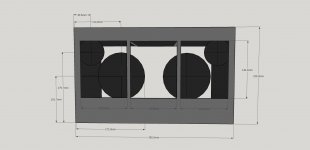
Holy cow, the 1st thing I'm seeing is that is going to be really tight for your chosen drivers.
I attached a quick sketch of where I'd put the drivers but it doesn't actually fit within your desired speaker cabinet width of <150mm. Let me know if this is what you were thinking. Perhaps a tweeter with a smaller face plate or in fact no face plate at all would be in order here.
Attachments
Mygyth,
Holy cow, the 1st thing I'm seeing is that is going to be really tight for your chosen drivers.
I attached a quick sketch of where I'd put the drivers but it doesn't actually fit within your desired speaker cabinet width of <150mm. Let me know if this is what you were thinking. Perhaps a tweeter with a smaller face plate or in fact no face plate at all would be in order here.
Man, Ill be honest, most of whats being said here now is going way over my head. Any alterations you think are wise feel free to propose. Tbh, I picked those drivers because they physically fit in the space i need them in. If they dont do that effectively because i did not understand how much volume a speaker actually needs to work, then going a smaller option may be best. I dont need to go Dayton, but i know i can get them at a reasonable price in my country and they have lots of information on their website like FRD and ZMA files.
Honestly, at this point, I feel like ive learned as much as im likely to without actually getting my hands dirty and putting some parts together. Im even open to a predesigned setup if you know one that would suit me.
Otherwise, if im going back to the drawing board, what were the flaws in my driver choice? What parameters should i be paying more attention to?
Honestly, at this point, I feel like ive learned as much as im likely to without actually getting my hands dirty and putting some parts together. Im even open to a predesigned setup if you know one that would suit me.
Have you considered a nice pair of 3 inch full rangers?
A small fullrange box can probally be better and easier to build. I've made a design for a friend who just started this hobby for a 25L vented box with a Mark Audio CHN110 fullrange driver in 12mm mdf wich is tuned to 45Hz. No crossover needed as this driver is very flat for a fullrange and gives enoguh bass due to high xmax for such a driver. The size will be (in 12mm plywood, don't use mdf) 25cm wide, 45cm high and 32cm deep with a 7cm round port in the front of 17,6cm long. Brace it with crossbracing from top to bottom, side to side and front to back (in an irregular way preferable) and damp the top, bottom and sides with 4mm bitumen. It models very well and should work, but Corona delayed the delivery of the driver so it's not build yet. An optional BSC can be added (but i don't thin it's really needed) with an 1,4mm 1,5mH inductor and a 3,9R resistor of 20w. Total cost of the project (a pair of those) will be arround 200€ including the cnc cutting of the wood at the woodshop .
And if you want to play very sure, build a tested kit, there are many around in a lot of shops. Google the kits you find and you will see if it's a good one. I would shop for kits (i'm in Belgium) at intertechnic, Jantzen or Lautsprechershop.de
And if you want to play very sure, build a tested kit, there are many around in a lot of shops. Google the kits you find and you will see if it's a good one. I would shop for kits (i'm in Belgium) at intertechnic, Jantzen or Lautsprechershop.de
Last edited:
Or maybe just keep that (good) tweeter and replace the woofer with an Dayton RS180-4. It's not that expensive (50-60€/$), fits the tweeter way better and can work in a sealed 20L cabinet for both drivers and the crossover. Fill as much the cabinet as possible wit polyfill. You will have a god response untill about 40Hz inroom and an F3 of 60Hz (wich is very good for this size of box). Box size in 18mm wood (ply or mdf) would be something like 25cm wide, 30xm deep and 40cm high (20.6L).
The crossover need to be adapted a bit, but this could do it. BSC is not calculated as i don't have the measurements, but in room it should not matter much (due to roomgain), also because the bass has a little lift.
The crossover need to be adapted a bit, but this could do it. BSC is not calculated as i don't have the measurements, but in room it should not matter much (due to roomgain), also because the bass has a little lift.
Attachments
.... what were the flaws in my driver choice? What parameters should i be paying more attention to?
Actually those are a pretty good choice for drivers. They work well together and the woofer only needs about 2L, it's got a pretty smooth FR and the rising response in the LF helps with baffle step compensation which means sensitivity will be just a little bit higher than a totally flat response. And it will go reasonably low in a vented box.
If I've got the dimensions about right in my diagram above, then it looks like you've got 2 choices:
1- to fit both of those drivers in the given "windows" the cabinets need to be about 180mm wide (but they don't need to be the full 235mm tall)
2 - change the tweeter selection to something smaller like one of these 2:
Peerless XT25SC40-04 1" Ring Radiator XT Tweeter 4 Ohm
Peerless by Tymphany OT19NC00-04 3/4" Fabric Dome Tweeter 4 Ohm
But that's if my diagram is correct. I don't have the radio in front of me. If you have a positioning of the drivers that fits, please let me know.
Actually, a 3rd choice would be Blake's suggestion of going with a smaller full range driver. I'd probably still stick with a tweeter because I suspect you will be listening off-axis pretty much all the time and full rangers are worse off-axis than smaller tweeters. But I looked at a few selections yesterday and I still liked your choice of the Dayton better. But maybe there's something I missed?
- Home
- Loudspeakers
- Multi-Way
- First project - Will this crossover design work?