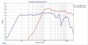
@system7 Thanks, just subbed in that woofer. Looks like i can get a decent crossover quite a bit cheaper (Image 1). Also should have a minimum of ~8.4Ohms impedence. Which, since i gather higher impedence is better makes this a significant upgrade on my last setup?
A couple of tips ... when viewing curves in X-Sim, look at the curves marked "S1", "S2" etc. The "driver only" curve is showing you what the driver itself would do... not what your crossover is doing with the driver.
From your last thumbnail, I would move R4 behind C4, this is to prevent it from carrying current all the time. I would try to adjust C2 without R2 in the circuit... If you right click on it you can temporarily short it and remove it later, if it's not helpful.
But it looks like you're getting close to a "first blush" design. Do keep in mind that computer simulation in XSim and it's cousins does not take your box or your room into consideration, so it is just a rough estimate at best.
Not bad for a beginner, though.
Yes, I echo the above - not bad for a beginner.
But you need to read this now - So you want to design your own speaker from scratch! - because your sims currently have 3 fatal flaws:
1) you must include baffle diffraction effects in your frd files
2) you have to account for the different acoustic centers of the drivers and their distance to your ears
3) you also have to extract minimum phase from both your frd and zma files and align each driver's phase in the xo region
I could also say that you haven't included the effects of your box on the woofer's FR and impedance files which are necessary for your design but with a 2-way with a high enough xo point, don't actually make much of a difference to the actual xo sims. Personally, I always include them anyways.
If you give us the dimensions of the old radio that you found, we might be able to make some further recommendations or even do up or double check your sims ourselves.
A couple more tips for XSim:
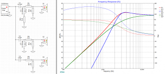
- in the FR graph, get rid of the phase for the system response too. It tells you nothing. Instead, check the "show with phase" box for S1 and S2. Now what you want to do is try to get those lines to match up as closely as possible in the region of the xo or in other words in the frequency range where the 2 drivers are both contributing to the summed response. Do this while at the same time keeping the summed response as flat as possible.
- you can get rid of the "driver only" curves in the Impedance graph as well
- to extract minimum phase from your files, go to the "Tune" window for each driver and for the FRD and ZMA phase source, select "derived" instead of "measured"
- in XSim, acoustic center differences are input in the "Tune" window under "mod delay" but it's a little complex.
Essentially, the acoustic center is the physical point of the driver from which the sound wave starts. It's always best to actually measure this with the drivers on the actual baffle, but for the purpose of simulations you can generally take that point to be where the cone of the driver meets the voice coil former or in the case of a tweeter dome where the dome meets the surround. The easiest way to do this is to blow up the drivers' pdf's to actual size on your computer screen and then take a physical measurement with a ruler.
One might think that the mod delay should then just be the difference between the 2 measurements but it's a little more complex than that because 1 driver is probably above the other in relation to your ears. So a little math is required.
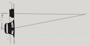
In the pic below:
A = your ears
B = the tweeter acoustic center
C = the woofer acoustic center
D = the distance between the center of the tweeter and the center of the woofer
E = the front of the baffle
So what you are trying to calculate is the difference in lengths from A to B and from A to C. To make things simple, assume the distance AE is 1 meter and lets say the acoustic center for the tweeter is 5mm back, the acoustic center for the woofer is 15mm back and that the center to center spacing between drivers is 100mm. So from our good old friend Pythagoras, the distance AE is going to be the square root of 1000^2 + 100^2 which equals 1005mm. So now the difference from A to C and from A to B is AC - AB = (1005 + 15) - (1000 + 5) = 15mm or .6".
Back in Xsim now, you leave the tweeter delay at 0 and input .6" for the delay of the woofer. Hope that makes sense.
But you need to read this now - So you want to design your own speaker from scratch! - because your sims currently have 3 fatal flaws:
1) you must include baffle diffraction effects in your frd files
2) you have to account for the different acoustic centers of the drivers and their distance to your ears
3) you also have to extract minimum phase from both your frd and zma files and align each driver's phase in the xo region
I could also say that you haven't included the effects of your box on the woofer's FR and impedance files which are necessary for your design but with a 2-way with a high enough xo point, don't actually make much of a difference to the actual xo sims. Personally, I always include them anyways.
If you give us the dimensions of the old radio that you found, we might be able to make some further recommendations or even do up or double check your sims ourselves.
A couple more tips for XSim:
- in the FR graph, get rid of the phase for the system response too. It tells you nothing. Instead, check the "show with phase" box for S1 and S2. Now what you want to do is try to get those lines to match up as closely as possible in the region of the xo or in other words in the frequency range where the 2 drivers are both contributing to the summed response. Do this while at the same time keeping the summed response as flat as possible.
- you can get rid of the "driver only" curves in the Impedance graph as well
- to extract minimum phase from your files, go to the "Tune" window for each driver and for the FRD and ZMA phase source, select "derived" instead of "measured"
- in XSim, acoustic center differences are input in the "Tune" window under "mod delay" but it's a little complex.
Essentially, the acoustic center is the physical point of the driver from which the sound wave starts. It's always best to actually measure this with the drivers on the actual baffle, but for the purpose of simulations you can generally take that point to be where the cone of the driver meets the voice coil former or in the case of a tweeter dome where the dome meets the surround. The easiest way to do this is to blow up the drivers' pdf's to actual size on your computer screen and then take a physical measurement with a ruler.
One might think that the mod delay should then just be the difference between the 2 measurements but it's a little more complex than that because 1 driver is probably above the other in relation to your ears. So a little math is required.
In the pic below:
A = your ears
B = the tweeter acoustic center
C = the woofer acoustic center
D = the distance between the center of the tweeter and the center of the woofer
E = the front of the baffle
So what you are trying to calculate is the difference in lengths from A to B and from A to C. To make things simple, assume the distance AE is 1 meter and lets say the acoustic center for the tweeter is 5mm back, the acoustic center for the woofer is 15mm back and that the center to center spacing between drivers is 100mm. So from our good old friend Pythagoras, the distance AE is going to be the square root of 1000^2 + 100^2 which equals 1005mm. So now the difference from A to C and from A to B is AC - AB = (1005 + 15) - (1000 + 5) = 15mm or .6".
Back in Xsim now, you leave the tweeter delay at 0 and input .6" for the delay of the woofer. Hope that makes sense.
Attachments
Sorry to but in again ... but higher doesn't mean better. It is a little easier on the amplifier because it draws less current, but that's about the only advantage.
"Better" generally comes from carefully matching drivers and box designs. In theory, the right drivers in the right box don't need a complex crossover. Sometimes it can be as simple as a single capacitor to keep bass energy out of the tweeter.
The crossover does play a role, of course, but mostly it's there to correct for our compromises.
What I meant by my previous post is that if you are doing a design and you get a real low dip in impedance someplace on the response curve, it could overheat and damage the amplifier... That is if you are designing for 8 ohms and at some point the impedance dips to 1 ohm, even while the rest is still at 8 or 10 ohms, your amp is at risk.
The opposite... that characteristic rise to 20 ohms or so at woofer resonance is not harmful. It's just hard to look at. 😀
Couldn't agree more, as stated re. Z, in my last post.
Perhaps some further help at this point would be beneficial.
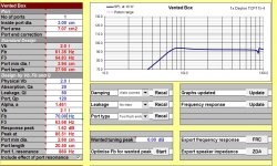
In my mind, no need to change the woofer yet. The 4ohm version gives you more sensitivity than the 8ohm and with small drivers that try to reach low, all the help in terms of SPL that you can get, the better. I would consider running it vented though as that's its preferred alignment and the F3 goes from about 120Hz sealed to about 64Hz in a vented box. About 2L tuned to 70Hz with a 3cm x 20cm port gives a little boost in the low end that matches the natural rising response of the woofer and helps a tiny little bit to compensate for baffle step loss. Max SPL though is going to unavoidably be a little low with small drivers like these when they are trying to run more or less full range. About 90/92dB at 1m. See pic 1.
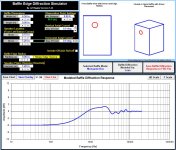
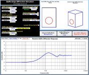
Just to show how diffraction can work and how important it is, pics 2 and 3 show baffle diffraction effects if you put the drivers on a 6.5" x 9.5" front baffle. Note that these are just examples because when you put the boxes into the old radio frame that you posted you are going to get something different again. That was why I asked if you could post the dimensions of that unit.
Pic 4 shows what the drivers' FR looks like when you add in the baffle diffraction and the vented box response to the woofer but before any xo work.
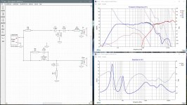
Pic 5 is a quick attempt in XSim given all the generated data. Minimum phase was derived for all frd and zma files when entering them into the program. Using the Dayton spec sheets, I arrived at acoustic centers for the tweeter of 7mm back and 25mm back for the woofer. Unfortunately, this was a bit of a guess as the woofer is not actually pictured scaled properly to the measurements given. So I took my best guess. After calculating path differences and converting to inches, I input a woofer delay of .87". Impedance for the woofer has also been changed to match its 2L vented box alignment. Note the double impedance peaks now in the LF instead of only the single one you get with a closed box.
I tried to use the minimum number of parts because with inexpensive drivers it doesn't make any sense to do otherwise. The summed response is decently flat, the drivers' phase align very well in the xo region, impedance is totally respectable for a 4ohm amp and the xo ends up at about 2600Hz. I might actually like steeper slopes in the xo for these 2 drivers, but as I say not really worth it to start adding more and more components.
Pic 6 is what the response looks like with my frd and zma files and the 2nd xo you attached in post #16. This is just to demonstrate how different the response can be if the original files going into the simulation are not quite accurate.
Hope that helps. Please let me know if you have any questions.
In my mind, no need to change the woofer yet. The 4ohm version gives you more sensitivity than the 8ohm and with small drivers that try to reach low, all the help in terms of SPL that you can get, the better. I would consider running it vented though as that's its preferred alignment and the F3 goes from about 120Hz sealed to about 64Hz in a vented box. About 2L tuned to 70Hz with a 3cm x 20cm port gives a little boost in the low end that matches the natural rising response of the woofer and helps a tiny little bit to compensate for baffle step loss. Max SPL though is going to unavoidably be a little low with small drivers like these when they are trying to run more or less full range. About 90/92dB at 1m. See pic 1.
Just to show how diffraction can work and how important it is, pics 2 and 3 show baffle diffraction effects if you put the drivers on a 6.5" x 9.5" front baffle. Note that these are just examples because when you put the boxes into the old radio frame that you posted you are going to get something different again. That was why I asked if you could post the dimensions of that unit.
Pic 4 shows what the drivers' FR looks like when you add in the baffle diffraction and the vented box response to the woofer but before any xo work.
Pic 5 is a quick attempt in XSim given all the generated data. Minimum phase was derived for all frd and zma files when entering them into the program. Using the Dayton spec sheets, I arrived at acoustic centers for the tweeter of 7mm back and 25mm back for the woofer. Unfortunately, this was a bit of a guess as the woofer is not actually pictured scaled properly to the measurements given. So I took my best guess. After calculating path differences and converting to inches, I input a woofer delay of .87". Impedance for the woofer has also been changed to match its 2L vented box alignment. Note the double impedance peaks now in the LF instead of only the single one you get with a closed box.
I tried to use the minimum number of parts because with inexpensive drivers it doesn't make any sense to do otherwise. The summed response is decently flat, the drivers' phase align very well in the xo region, impedance is totally respectable for a 4ohm amp and the xo ends up at about 2600Hz. I might actually like steeper slopes in the xo for these 2 drivers, but as I say not really worth it to start adding more and more components.
Pic 6 is what the response looks like with my frd and zma files and the 2nd xo you attached in post #16. This is just to demonstrate how different the response can be if the original files going into the simulation are not quite accurate.
Hope that helps. Please let me know if you have any questions.
Attachments

I see a lot of good thoughts, but some strange circuits for this crossover. But BSC and time alignment are indeed rather essential for a good crossover. You can do it acousticly (make sure in the box that all drivers are aligned) or in the crossover.
I did follow the example of the poster above, and used the published files the way he did (derived and so) in Xsim and used my logical way of building a cr and it's a bit different, but better i think. I don't get why you use resitors on the parallel inductors and caps in a crossover.
Anyway, this is my take... The Zorbel before the filters is optinional, but makes the speaker easier to drive by amps. Sometimes amps can't handle high impendance spikes and it influences the sound.
Attachments
Last edited:
Hey waxx
I've used the extra resistors in the parallel legs for several reasons:
1 - they help to shape the response around the knee of each filter
2 - they help to decrease the conductivity to ground in the parallel legs (not that that is much of a problem here with the values I'm using)
3 - they cost next to nothing to do so
4 - and they fine tune and help align each driver's phase response in the xo region, helping to overcome the problem of the physically unaligned acoustic centers of the drivers on a vertical baffle
You'll need to display each drivers' phase in XSim to see how your design meets that last criteria. That's also a fairly large dip in the response between about 250Hz and 1500Hz. More than I'd be happy with. And I also have to wonder if you have included baffle step loss accurately as your LF response is showing no SPL loss from the spec sheet's infinite baffle measurements. It should be down somewhere around 6dB from the spec sheet's 85/86dB in that area.
Hey waxx
I've used the extra resistors in the parallel legs for several reasons:
1 - they help to shape the response around the knee of each filter
2 - they help to decrease the conductivity to ground in the parallel legs (not that that is much of a problem here with the values I'm using)
3 - they cost next to nothing to do so
4 - and they fine tune and help align each driver's phase response in the xo region, helping to overcome the problem of the physically unaligned acoustic centers of the drivers on a vertical baffle
Thanks for that, i'll experiment with it.
You'll need to display each drivers' phase in XSim to see how your design meets that last criteria.
How do yo do that, i don't see that option
And I also have to wonder if you have included baffle step loss accurately as your LF response is showing no SPL loss from the spec sheet's infinite baffle measurements. It should be down somewhere around 6dB from the spec sheet's 85/86dB in that area.
I used the files from Dayton Audio their website. If i would build this for real, i would work on measurings from the drivers in the box off course. But here it was more a study of the case like presented by the OP... I don't have these drivers or am building the box...
Actually i just found how to do that, and used your explenation in my next version. And it's indeed better. And i could drop the zorbel, as even the most demanding amp that runs 4R can load this..
And Again i learned something on this wonderfull forum... Thanks!
And Again i learned something on this wonderfull forum... Thanks!
Attachments
Last edited:
waxx, I'm liking your latest version better now. On the plus side, you've got a flatter FR and the phase is decently aligned around the xo.
On the negative side, the tweeter resonance frequency of about 1100Hz is only about 11 or 12dB down from the summed response. That's worrisome. Throwing a resonance compensation filter on it would help or else going to a steeper xo slope by adding a 2nd series capacitor would do it as well at lower cost.
Also, no argument from me that measurements are the way to go but when that's not possible or if just trying to improve the accuracy of the simulations, then it's imperative to include the baffle diffraction effects. These too can be simulated and then added in to frd files as I've done above. Frequency Response Modeler will do both of those things as well as more (like splicing in the modeled LF sealed or vented response) but it's an Excel program which not everybody has access to. In that case switching to an all-in-one program like VituixCAD might be the way to go.
And yup, learning is definitely cool.
Hey Mygyth, your silence since I 1st posted has me feeling like I have somehow discouraged you on your project which wasn't my intention. My apologies if that is the case.
I'd actually be happy to work up some sims for you if you can give me a little further information.
- the radio dimensions
- how low in frequency you want it to go (are you using a sub maybe too?)
- how loud you might like it to go
- and if it will sit on a shelf up against a wall in which case I'll need to modify the baffle diffraction sims
waxx, I'm liking your latest version better now. On the plus side, you've got a flatter FR and the phase is decently aligned around the xo.
On the negative side, the tweeter resonance frequency of about 1100Hz is only about 11 or 12dB down from the summed response. That's worrisome. Throwing a resonance compensation filter on it would help or else going to a steeper xo slope by adding a 2nd series capacitor would do it as well at lower cost.
Also, no argument from me that measurements are the way to go but when that's not possible or if just trying to improve the accuracy of the simulations, then it's imperative to include the baffle diffraction effects. These too can be simulated and then added in to frd files as I've done above. Frequency Response Modeler will do both of those things as well as more (like splicing in the modeled LF sealed or vented response) but it's an Excel program which not everybody has access to. In that case switching to an all-in-one program like VituixCAD might be the way to go.
And yup, learning is definitely cool.
I can't make that old excell file work with my legit MS excell. It crashes, gives security errors all the time and is totally unstable and unusable... And i'm a system admin as profession. I don't doubt Jeff Bagby's skills as speaker builder, but this excell sheet is not build like it should. I think it's made in a very old version, and then adapted, but excell changed a lot in the last decenium...
Virtuaxcad is working, but i still need to figure out a lot how it works. It seems that most good software is made way to complex and hard to work with. Those engineers that work on that should higher a software architect who can make better layouts and logical ways of working (with the same functionality), wich would make it way more easy for hobbiest like me to work with it...
But still great that those exist. And i'll figure it out. But mostly i calculate my bsc by hand (much faster), and compensate with a rise in the crossover in xsim. I know how it works and know the math behind it, so that is not so difficult.
Hello Waxx ...
Please first see my comments in THIS THREAD
First a disclaimer ... I don't have the exact specs for your drivers. So the values you will see are an approximation, but they should be close. It would help if you could upload your DXO file from XSim.
I jacked the amplifier up to 100 watts and opened the current panel...
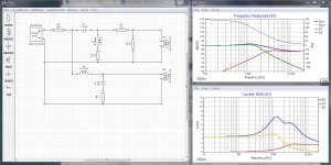
Take a look at thumbnail #1 ... Notice the current on R5 (which simulates the speaker wire) Notice that you have a lot of current flowing that is not reaching your drivers. This is bad. In fact, it reaches nearly 5 amps of wasted current.
On a 100 watt amplifier, you should reasonably expect to draw no more than 3.5 amps on an 8 ohm load. The problem would be even worse for a 4 ohm design.
This is because your lead cap on the tweeter chain (c1) is too large. This brings excessive current into the tweeter filter that you then have to aggressively remove with L1 and R3. In fact, there is a point where R3/L1 are carrying almost twice as much current as your driver.
The same problem exists in your woofer chain. L2 is far too small, so you end up aggressively removing current with the c2/r4 chain which is again handling more current than your driver.
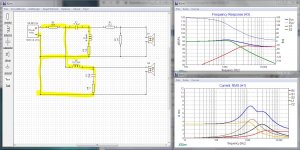
See thumbnail #2... I've highlighted the current paths for you.
This crossover will be very inefficient and might even overheat or damage an amplifier.
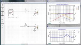
The solution is to start from a first order filter and get your crossover point where you want it. Then add parts reluctantly, keeping in mind that any current flowing that does not go through a driver is just wasted energy.
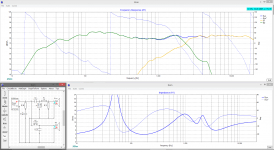
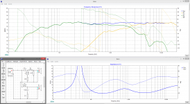
See thumbnail #3 ... This is an example of where to start.
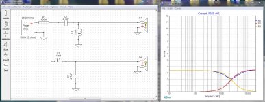
As in thumbnail 4, any parts beyond this basic first order crossover should be to correct minor errors... not to hammer the thing into shape. Basically the second order parts are just to sharpen the driver roll-offs and smooth the frequency response, they should be handling only very small currents.
Hope this helps...
Please first see my comments in THIS THREAD
First a disclaimer ... I don't have the exact specs for your drivers. So the values you will see are an approximation, but they should be close. It would help if you could upload your DXO file from XSim.
I jacked the amplifier up to 100 watts and opened the current panel...
Take a look at thumbnail #1 ... Notice the current on R5 (which simulates the speaker wire) Notice that you have a lot of current flowing that is not reaching your drivers. This is bad. In fact, it reaches nearly 5 amps of wasted current.
On a 100 watt amplifier, you should reasonably expect to draw no more than 3.5 amps on an 8 ohm load. The problem would be even worse for a 4 ohm design.
This is because your lead cap on the tweeter chain (c1) is too large. This brings excessive current into the tweeter filter that you then have to aggressively remove with L1 and R3. In fact, there is a point where R3/L1 are carrying almost twice as much current as your driver.
The same problem exists in your woofer chain. L2 is far too small, so you end up aggressively removing current with the c2/r4 chain which is again handling more current than your driver.
See thumbnail #2... I've highlighted the current paths for you.
This crossover will be very inefficient and might even overheat or damage an amplifier.
The solution is to start from a first order filter and get your crossover point where you want it. Then add parts reluctantly, keeping in mind that any current flowing that does not go through a driver is just wasted energy.
See thumbnail #3 ... This is an example of where to start.
As in thumbnail 4, any parts beyond this basic first order crossover should be to correct minor errors... not to hammer the thing into shape. Basically the second order parts are just to sharpen the driver roll-offs and smooth the frequency response, they should be handling only very small currents.
Hope this helps...
Attachments
Last edited:
On the other hand, the damped C-RL can give a response that you won't find with first or second order.
It's about current, Allen.
His circuit was threatening to pull almost 8 amps from a 100 watt amplifier most of which was wasted in shunts to ground... it would for certain overheat the amplifier and it might even damage it. No matter what trickery the filters are up to, it's not worth it if it's going to kill an expensive piece of equipment.
Last edited:
Hey guys, sorry for being awol. Im a shift worker, and im really only working on this project on my days off. I havnt yet read through all of the comments you guys have left, but what i have read looks super helpful, and im looking forawrd to reading the rest. Thanks guys. I think the enclosure im hoping for is a bit smaller than what some of you are thinking, but ill do some measurments and put up a blueprint today, along with some more detailed responces to your feedback.
In this particular case.. the impedance stays above 4 ohms at all frequencies. It should be fine.Douglas Blake said:..if it's going to kill an expensive piece of equipment
In this particular case.. the impedance stays above 4 ohms at all frequencies. It should be fine.
Even though it's wasting 50% of the energy the amplifier produces?
I would expect such a speaker to sound weak or distant. It's efficiency would be abysmally low.
There is more to this than simple impedance and frequency response curves.
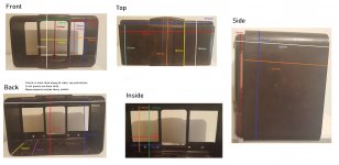
Ok so heres what i have blueprintwise. I hope its not too confusing.
The bottom line is that due to bevels in the internal structure, the speakers can either be 222mm high x 160mm deep x 115-150mm wide
Or they can be 210mm high x 178mm deep x 115-145mm wide.
Logistically, those first set of measurments are preferable to me. I could maybe make them go a bit deeper, but they would be sticking out the back of the enclosure.
These measurements include whatever material will be used to make the enclosure. Please note that any vent will have to factor in the size of the front holes.
Thats assuming that a left and a right speaker make sense in this space. That was my original plan, and id like to make that happen, but Im open to suggestions. Be that smaller drivers, a different style of enclosure, a single larger speaker, or something else.
Attachments
Hey Mygyth, your silence since I 1st posted has me feeling like I have somehow discouraged you on your project which wasn't my intention. My apologies if that is the case.
I'd actually be happy to work up some sims for you if you can give me a little further information.
- the radio dimensions
- how low in frequency you want it to go (are you using a sub maybe too?)
- how loud you might like it to go
- and if it will sit on a shelf up against a wall in which case I'll need to modify the baffle diffraction sims
Thanks man. I actually started reading the tutorial you linked as well as the documents linked in it (although i had already done AllenB's CO tutorial). I did get a bit overwhelmed by the influx of info. Definitely not giving up though. Thanks for your help 🙂
- I have provided detailed dimensions in my above post
- Im not sure what frequencies to shoot for, but this will be mostly used for music and podcasts. I do like nice bassy music as well as classic rock... Really anything but rap and metal (sorry to fans of those genres, i envy you your joy, but i cant seem to share it). As its in a workshed, i dont have an exact listening distance. So I expect some loss of fidelity anyway. I guess making something robust and easy to listen to for hours is more important than something with perfect range.
- loud enough to cover the sound of powertools would be excellent
- I expect it will sit on a shelf, but i can pull it out from the wall a bit if that makes the designs easier.
Thanks again for your input 🙂
- Home
- Loudspeakers
- Multi-Way
- First project - Will this crossover design work?