Can you indicate me the brand - number of this mosfet, and if it is possible a place to find one?
Many thanks
Many thanks
You'll be surprised the data needed is written all over it, only that you'll have to remove it from the PCB first. Farnell stock them, 24 hours delivery in EU.
Helo Everyone,
LC may I have your attention on my request please, I m wondering about the recomened R3/R4 resistor value to cope with different rail voltage in my case being 45V and 52V and if you have the data, what can be the expected power output within normal thd ? then I can rework my 6 modules and check results according to your guidance.
many thanks and sorry in advance if this a bit borring but I think not all of your customer bought an hypex 63V 🙄
I'm in a same boat- just going to finish putting FO1.4m amplifier modules + Hypex smps1200A180 (46V) in a case and already interested to ask:Helo Everyone,
LC may I have your attention on my request please, I m wondering about the recomened R3/R4 resistor value to cope with different rail voltage in my case being 45V and 52V and if you have the data, what can be the expected power output within normal thd ? then I can rework my 6 modules and check results according to your guidance.
many thanks and sorry in advance if this a bit borring but I think not all of your customer bought an hypex 63V 🙄
1. Do I need to swap R3/R4 to a 100ohm resistors for an optimal performance?
2. What would be recommended bias settings for using this module with 46V power supply?
3. Will it be possible to order a FO1.4M amplifier already preconfigured for a 46V (as I could be interested to buy one more pair of amplifier modules in a near future)?
Sorry to ask.
These modules. When you turn them on. Are there any "thumbs" or noise in the speakers?
These modules. When you turn them on. Are there any "thumbs" or noise in the speakers?
You'll be surprised the data needed is written all over it, only that you'll have to remove it from the PCB first. Farnell stock them, 24 hours delivery in EU.
You are right. I´m surprised, the mosfet (ALF1616W) is out of production.
Regards
At low PSU voltage, resistors R3, R4 could be changed to 100 R (220 R default value), SMD1206 case, for higher VAS bias setup. Set TR1, TR2 to zero Ohm before turning on the FO M. 😎
Lazy cat, I just bought 100R resistors to change R3, R4 and showed this amplifier to a tech guy, who could swap these resistors. For now it seems, that R3 and R4 are 2200R not 220R. Can you clarify please?
2200 on SMD resistor means: 220 Ohm, 1 % (220*10^0=220)
221 on SMD resistor means: 220 Ohm, 5 % (22*10^1=220)
2202 on SMD resistor means: 22 kOhm, 1 % (220*10^2=22000)
221 on SMD resistor means: 220 Ohm, 5 % (22*10^1=220)
2202 on SMD resistor means: 22 kOhm, 1 % (220*10^2=22000)
All of you trying low PSU voltage to supply FO M:
- desolder R3, R4, 2200 resistors (1206 SMD)
- rotate trimmers TR1, TR2 CCW to min resistance
- turn power on and set the trimmers to get 180 mV (ie. 18 mA) between TP1-TP2 (same between TP3-TP4) and zero DC offset
- turn power off and measure TR1, TR2 resistance (on board resistance, without desoldering them)
- calculate R3, R4 in a way that these in parallel with trimmers in mid position (these are 12 turn trimmers) will give measured resistance. R3 is in parallel with trimmer TR1, R4 is in parallel with trimmer TR2
- get correct R3, R4 and solder them to PCB
LC,
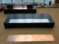
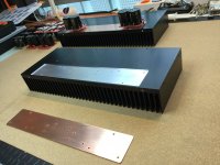
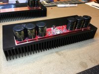
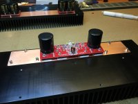
When you mounted the CapBanks on the heatsink (#3467), why did you use that strip of aluminium? Also, did you apply any thermal compound between the strip and the heatsink? )
Thanks.
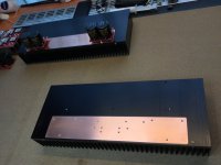
It's a copper strip, serving to spread thermal energy from mosfets to the heatsink faster. At the same time copper serves as a very good EMI protection since high frequency signals are shorted in copper (thermal effect of eddy currents) and sent to earth via chassis' earth connection. More here:
https://en.m.wikipedia.org/wiki/Eddy_current
Attachments
-
 IMG_0670.JPG718 KB · Views: 593
 -
 IMG_0671.JPG776 KB · Views: 568
 -
 IMG_0672.JPG797.4 KB · Views: 545
 -
 IMG_0673.JPG735.7 KB · Views: 547
 -
 IMG_0680.JPG884.1 KB · Views: 279
 -
 IMG_0678.JPG698.6 KB · Views: 237
 -
 IMG_0677.JPG794.4 KB · Views: 211
 -
 IMG_0674.JPG760.8 KB · Views: 516
 -
 IMG_0681.JPG864.1 KB · Views: 269
 -
 IMG_0682.JPG709.5 KB · Views: 235
Last edited:
You are right. I´m surprised, the mosfet (ALF1616W) is out of production.
Regards
No worries, Profusion will be glad to sell you as many as you like, directly.
Last edited:
Thanks for the Q.Sorry to ask.
These modules. When you turn them on. Are there any "thumbs" or noise in the speakers?
Well Hypex SMPS goes from 0 V to +/-63 V (126 V) or +/-85 V (170 V) in a few micro seconds (very steep pulse' rise time), FO M and FO L are so fast that both settle their outputs to 0 V in this few micro seconds of settling time. No thumb or noise generated.
Now try this with other amps connected to the loudspeakers directly, like FO M and FO L are.
Last edited:
Hi L.C.
I can't wait to listen to the FO L. I am preparing the case and the ps waiting for the modules to arrive. 🙂
When you turn off the modules, with the extra capacitors connected, is there any noise in the speakers ?
Is there a need for output relays when using extra capacitors?
I can't wait to listen to the FO L. I am preparing the case and the ps waiting for the modules to arrive. 🙂
When you turn off the modules, with the extra capacitors connected, is there any noise in the speakers ?
Is there a need for output relays when using extra capacitors?
Last edited:
It's a copper strip, serving to spread thermal energy from mosfets to the heatsink faster. At the same time copper serves as a very good EMI protection since high frequency signals are shorted in copper (thermal effect of eddy currents) and sent to earth via chassis' earth connection. /QUOTE]
Would it be correct to assume by your response that you didn't use any thermal compound?
Thermal compound used on all surfaces, also in between copper strip and heatsink.Would it be correct to assume by your response that you didn't use any thermal compound?
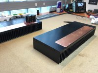
380 mm x 50 mm x 150 mmLC,
What's the dimensions of the heatsink in post #3631?
FO L bias set to 400 mA power supply current.
FO M Audiopuls Review 10/10
Please find new First One M Audiopuls Review 🙂
https://translate.google.com/transl...ovi/2017/first-one-v1.4-amplifier/review.html
Please find new First One M Audiopuls Review 🙂
https://translate.google.com/transl...ovi/2017/first-one-v1.4-amplifier/review.html
Attachments
- Home
- Vendor's Bazaar
- First One - mosFET amplifier module