Hi Back,
I won't be able to tell since I set it at 280mA many months ago and won't be able to remember exactly how it sounded like if it was A/B test.
I'll tell you about the 380mA setup for sure. With my chassis I could potentially even go to 600mA but I don't know if the SMPS would like that. Won't try that anyways!
Ciao!
Do
ok thanks anyway.
Maybe it slipped my attention, but I can't remember if it was mentioned. Can Cresnet SMPS handle the extra 10mF Mundorf caps?
Maybe it slipped my attention, but I can't remember if it was mentioned. Can Cresnet SMPS handle the extra 10mF Mundorf caps?
can handle 6mf.
@Bassivus
SMPS-600 can take up to 6800uF per rail, in addition to the on board 2200uf.
Using soft start module with the SMPS is a big plus at that capacitance.
SMPS-600 can take up to 6800uF per rail, in addition to the on board 2200uf.
Using soft start module with the SMPS is a big plus at that capacitance.
@Cresnet & back
Thanks! It seems good enough to me 🙂 I think I'll go with Cresnet SMPS too.
i am very happy with it.
@Bassivus
SMPS-600 can take up to 6800uF per rail, in addition to the on board 2200uf.
Using soft start module with the SMPS is a big plus at that capacitance.
Are these 6800uF per rail the "extra CDE LX381" Danny used perhaps with its nice Cresnet built?
Are these 6800uF per rail the "extra CDE LX381" Danny used perhaps with its nice Cresnet built?
Yes they are.
The new SMPS will tolerate much larger values, I expect a minimum of 15000uF per rail.
Yes they are.
The new SMPS will tolerate much larger values, I expect a minimum of 15000uF per rail.
Nice! 🙂 When can we expect them available ?
Yes they are.
The new SMPS will tolerate much larger values, I expect a minimum of 15000uF per rail.
you are building a new one?
give us some info.
same power?
@Bassivus
SMPS-600 can take up to 6800uF per rail, in addition to the on board 2200uf.
Using soft start module with the SMPS is a big plus at that capacitance.
Why not design a circuit keeping the extra caps under voltage let us say 6Vdc when shutting down the SMPS ?
Seems to be better for the caps .
... Or why not integering directly a softstart function within the new SMPS, given their use is known - it could also protect you in terms of potential probs with some careless customers...
More and more interested!
More and more interested!
... Or why not integering directly a softstart function within the new SMPS, given their use is known - it could also protect you in terms of potential probs with some careless customers...
More and more interested!
+1 the hypex have build in soft start.
Hello Guys, question about VAS bias vs supply voltage;
I m tuning a FO1.4 for a friend, using SMPS delivering 45volts
the original VAS bias setting we see is in the range of 25mv instead of 180mv (for recommended 18ma).
So it seem the VAS bias set in the factory for 63V is not ok for 45V.
Then I move it up to 180mv. ok.
The problem is that I have lot of thd (imd in fact) and I need to increase the VAS bias up to 280mv (28ma) to have a nice FFT at 80W into 6 ohms (15.6volt rms).
unfortunately I m stuck, I cannot rise up to 100W (1 more db) for 17v9, the IMD becomes imediately crazy.
FYI the heatsink temperature is around 41°C (unless I make a long test of course)
FYI the PSU delivers 43V (2V loss) at 80Watt.
any idea or advice ? LC , would it be better to change a resistor somewhere and then going back to 18ma...?
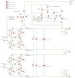
At low PSU voltage, resistors R3, R4 could be changed to 100 R (220 R default value), SMD1206 case, for higher VAS bias setup. Set TR1, TR2 to zero Ohm before turning on the FO M. 😎
Hello Guys, question about VAS bias vs supply voltage;
I m tuning a FO1.4 for a friend, using SMPS delivering 45volts
the original VAS bias setting we see is in the range of 25mv instead of 180mv (for recommended 18ma).
So it seem the VAS bias set in the factory for 63V is not ok for 45V.
Then I move it up to 180mv. ok.
The problem is that I have lot of thd (imd in fact) and I need to increase the VAS bias up to 280mv (28ma) to have a nice FFT at 80W into 6 ohms (15.6volt rms).
unfortunately I m stuck, I cannot rise up to 100W (1 more db) for 17v9, the IMD becomes imediately crazy.
FYI the heatsink temperature is around 41°C (unless I make a long test of course)
FYI the PSU delivers 43V (2V loss) at 80Watt.
any idea or advice ? LC , would it be better to change a resistor somewhere and then going back to 18ma...?
Hi !
What is your present setup ?
Speakers, PSU, input voltage ?
JMK
The question is that there are all these capacitors after the PS. Will they discharge in case of DC fault ?
This is clearly an issue. Imho extra capacitors defeat the whole purpose of this DC protection.
I'm currently looking for a good solution, I added 2x10000µF M-Lytic per channel, and it leads to:
- an even better sound, more warmth, more stability on complex music, definitively a must
- LC DC protection is prolly totally ineffective
- on power off, with no relay to cut outputs, sound can be listened for at least 20 seconds (while without caps it's something like 2-3 seconds, it depends on load), slowly degrading, and prolly not very good for speakers (symmetry, DC?)
So, i'm looking for a good, simple and compact solution to ensure protection and smooth on/off behavior (on is ok atm, off is not a "ploc" but rather a slow worrying sound one wants to avoid in such high end amps).
Since i'm controlling the amp through an arduino, i may use it to control relays, and detect DC protection status, or i may go for a usual speaker protection (but no AC here), or a mix.
Advices are welcomed 😉
A small calculation, supposing the SMPS switches of immediately with 20mF behind the protection:
It doesn't feel like being that much. The heat will be negligible, but what about the movement the cones will make?
Anyway, I wouldn't trust discharging 20mF @ 63V straight into my PMC-speakers...
I have since 7 years a Hypex UCD400HG, driven by a DIY linear Power Supply. In the PS, I incorporated a DC-protection, with the relais at the output of the PS instead of at the output of the amp. An idea that I took from one or another forum.
As I do tests and changes from time to time, the protection has played it's role several times. I'm really happy I have it there, and I put a DC-protection in other amps I make if I plan to play around with them.
I'm now building a first One M, with the same linear Power supply, with integrated DC-protection. I know everyone here says a SMPS sounds better, but I can't imagine that with 20mF behind a SMPS, and 20mF in a linear PS there will be much difference left. I will keep some free space in the cabinet to be able to switch between the transfo and an SMPS going into the capacitor-bank. That will make it easy to compare. Maybe I should keep some space for the Hypex-modules as well. That would be interesting.
- 20mF @ 63V = 1,26 Coulomb
- 1,26 Coulomb equals 0,011 Wh or (a fake unit) 39,6 Wsec.
- This means the capacitors can deliver 39,6 Watts during 1 second.
- 63V @ 8 Ohm = 7 Amps
- 63V x 7 Amps = 441 Watt
- This means the capacitors will deliver 441 Watts during +/- 0,1 second (OK, that's very rough, but just to give an idea).
It doesn't feel like being that much. The heat will be negligible, but what about the movement the cones will make?
Anyway, I wouldn't trust discharging 20mF @ 63V straight into my PMC-speakers...
I have since 7 years a Hypex UCD400HG, driven by a DIY linear Power Supply. In the PS, I incorporated a DC-protection, with the relais at the output of the PS instead of at the output of the amp. An idea that I took from one or another forum.
As I do tests and changes from time to time, the protection has played it's role several times. I'm really happy I have it there, and I put a DC-protection in other amps I make if I plan to play around with them.
I'm now building a first One M, with the same linear Power supply, with integrated DC-protection. I know everyone here says a SMPS sounds better, but I can't imagine that with 20mF behind a SMPS, and 20mF in a linear PS there will be much difference left. I will keep some free space in the cabinet to be able to switch between the transfo and an SMPS going into the capacitor-bank. That will make it easy to compare. Maybe I should keep some space for the Hypex-modules as well. That would be interesting.
Attachments
- Home
- Vendor's Bazaar
- First One - mosFET amplifier module